
Cross cutting PDC (Polycrystalline Diamond Compact) drill bit and design method

A drill bit and cutting tooth technology, which is applied in the field of cross-cut PDC drill bit and design, can solve the problems of wear speed difference, reduce the overall performance of the drill bit, and poor wear balance of cutting teeth, so as to ensure cleaning and cooling conditions, improve wear balance and Ingestion ability and effect of reducing wear rate

Pending Publication Date: 2022-05-24
SOUTHWEST PETROLEUM UNIV +1
View PDF0 Cites 0 Cited by
  • Summary
  • Abstract
  • Description
  • Claims
  • Application Information

AI Technical Summary

Problems solved by technology

Third, the wear rate of the PDC teeth on different radial areas of the PDC bit is significantly different. Generally, the wear rate of the cutting teeth in the outer area of ​​the drill bit (especially the outer 1 / 3 area of ​​​​the drill bit radius) is significantly faster than that of the teeth in the center area. Poor tooth wear balance, which reduces the overall performance of the drill bit

Method used


Image

  • Cross cutting PDC (Polycrystalline Diamond Compact) drill bit and design method
  • Cross cutting PDC (Polycrystalline Diamond Compact) drill bit and design method
  • Cross cutting PDC (Polycrystalline Diamond Compact) drill bit and design method

Examples


Embodiment 1

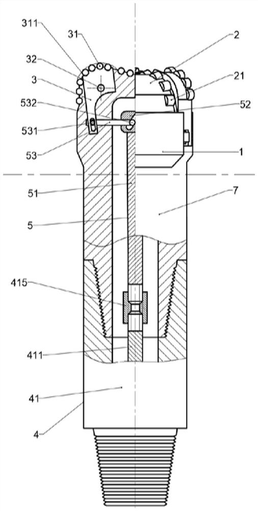
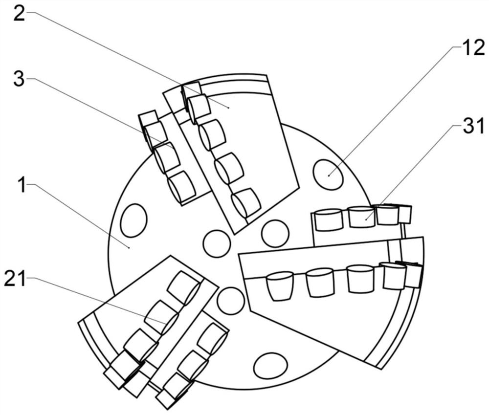
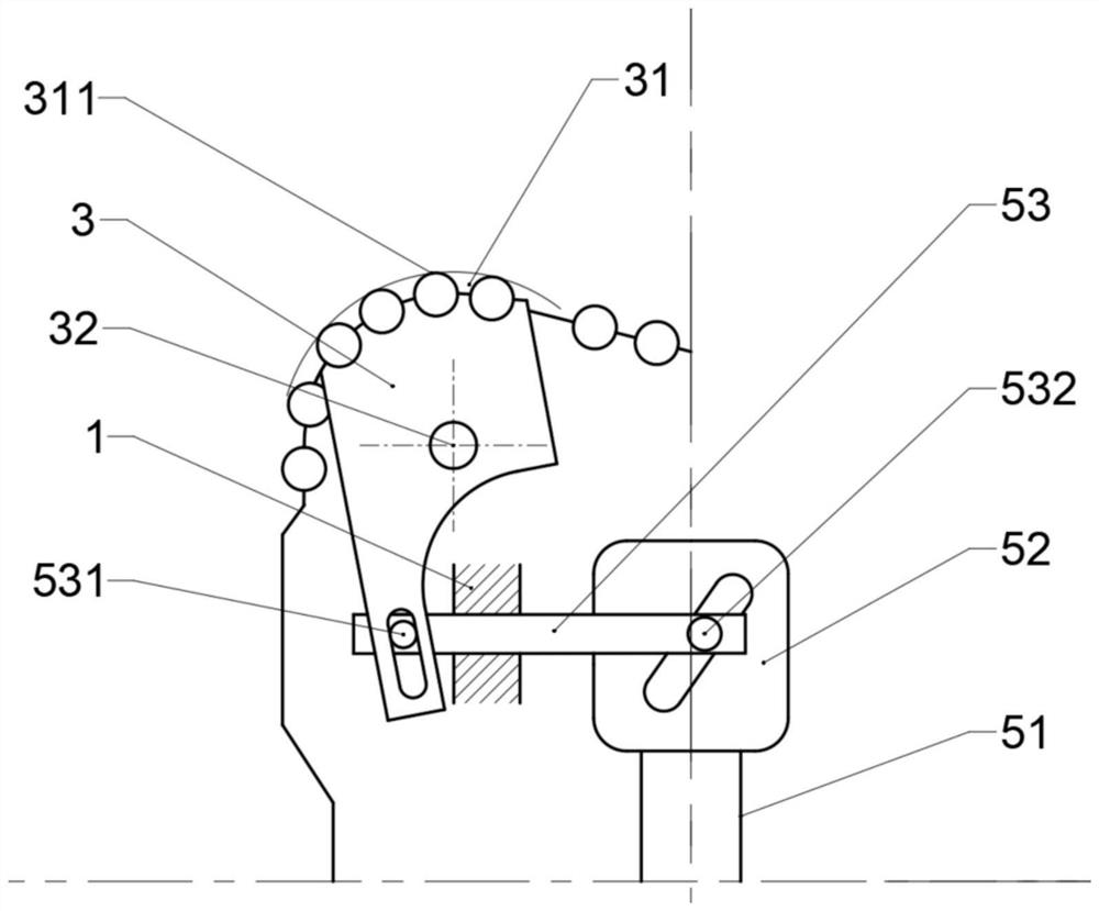
[0073] like Figure 1 to Figure 7 As shown, a cross-cutting PDC drill bit and design method include a drill bit body 1, a water hole 12 and a fixed cutting structure 2 fixed on the drill bit body 1, and a first group of cutting teeth 21 are arranged on the fixed cutting structure. The drill bit also includes a movable cutting structure 3 with a second row of cutting teeth 31, an axial push-pull short section 4 provided with an axial reciprocating motion generator 41, and a transmission mechanism 5. The transmission mechanism 5 adopts a cam mechanism, including an input shaft 51, Cam 52 and push rod 53.

[0074] The first set of cutting teeth 21 and the second set of cutting teeth 31 arranged on the cutting structure of the drill bit are polycrystalline diamond compacts, and can also be thermally stable polycrystalline diamond, natural diamond and impregnated diamond.

[0075] The drill bit body 1 adopts a split structure and is formed by connecting an axial push-pull short se...

Embodiment 2

[0087] This embodiment is basically the same as Embodiment 1, except that the movable cutting structure 3 is arranged on the rear side of the fixed cutting structure 2, such as Figure 14 shown.

Embodiment 3

[0089] This embodiment is basically the same as the embodiment 1, and the difference lies in that: the movable cutting structure 3 is arranged between the two fixed cutting structures 2 and 2', such as: Figure 15 shown.


PUM


Abstract

The invention discloses a cross cutting PDC drill bit and a design method, and belongs to the field of rock breaking tools for drilling equipment for petroleum and natural gas, mine engineering, building foundation engineering construction, geology, hydrology and the like, the cross cutting PDC drill bit comprises a drill bit body and a fixed cutting structure fixedly connected to the drill bit body, and a first set of cutting teeth is arranged on the fixed cutting structure; the drill bit further comprises a movable cutting structure with a second group of cutting teeth, an axial reciprocating motion generator and a transmission mechanism, and the movable cutting structure is driven by the axial reciprocating motion generator and the transmission mechanism; and the second group of cutting teeth on the movable cutting structure also generate reciprocating change of the radial position while doing circumferential motion along with the drill bit body. When the drill bit rotatably drills in a well, the cutting motion tracks of the first group of cutting teeth and the second group of cutting teeth on the well bottom are mutually crossed, so that crossed cutting is realized, and the rock breaking efficiency and the invasion capability of the drill bit are improved.

Description

technical field [0001] The invention belongs to the field of rock-breaking tools for drilling equipment such as petroleum and natural gas, mining engineering, building foundation engineering construction, geology, hydrology, etc., and specifically relates to a cross-cutting PDC drill bit and a design method. Background technique [0002] The drill bit is a rock-breaking tool used in drilling engineering to break the rock and form the wellbore. [0003] Polycrystalline diamond compact bits (ie PDC bits) are one of the main bits used in drilling engineering. Relying on high-hardness, wear-resistant, self-sharpening polycrystalline diamond composite sheet to shear and break rock, PDC bit is obtained in drilling engineering due to its high ROP, long life and low drilling cost in soft to medium-hard formations. widely used. [0004] The crown profile (also known as the cutting profile) is one of the important structural features of the drill bit, which is closely related to the...

Claims


Application Information

Patent Timeline
IPC IPC(8): E21B10/43E21B10/54E21B10/62
CPCE21B10/43E21B10/54E21B10/62
Inventor 杨迎新刘畅蔡灿李纪锐任心禹牛世伟黄奎林
Owner SOUTHWEST PETROLEUM UNIV
Learn More