
Automatic unloading equipment for reactor catalyst

A catalyst and reactor technology, applied in the field of reactor catalyst automatic unloading equipment, can solve problems such as difficulty, polluted gas in the working environment, uneven size of debris, etc., and achieve the effect of easy adjustment and flexible cutting process

Active Publication Date: 2022-05-24
JIANGSU TIANPENG PETROCHEMICAL TECH CO LTD
View PDF12 Cites 0 Cited by
  • Summary
  • Abstract
  • Description
  • Claims
  • Application Information

AI Technical Summary

Problems solved by technology

This type of catalyst will deposit petroleum carbon deposits and a large amount of metal salts during use, resulting in compaction of small particle catalysts
For some devices, severely hardened catalysts require a lot of labor and special equipment. The cleaning process takes a long time, and the working environment has polluting gases. Long-term operation is prone to safety hazards; during the cleaning process, a large amount of debris will remain, and Due to the uneven size of broken debris, there will be problems of clogging the suction pipe, resulting in low cleaning efficiency and difficulty

Method used


Image

  • Automatic unloading equipment for reactor catalyst
  • Automatic unloading equipment for reactor catalyst
  • Automatic unloading equipment for reactor catalyst

Examples


Embodiment Construction

[0025] The technical solutions in the embodiments of the present invention will be clearly and completely described below with reference to the accompanying drawings in the embodiments of the present invention. Obviously, the described embodiments are only a part of the embodiments of the present invention, rather than all the embodiments. Based on the embodiments of the present invention, all other embodiments obtained by those of ordinary skill in the art without creative efforts shall fall within the protection scope of the present invention.

[0026] In order to make the above objects, features and advantages of the present invention more clearly understood, the present invention will be described in further detail below with reference to the accompanying drawings and specific embodiments.

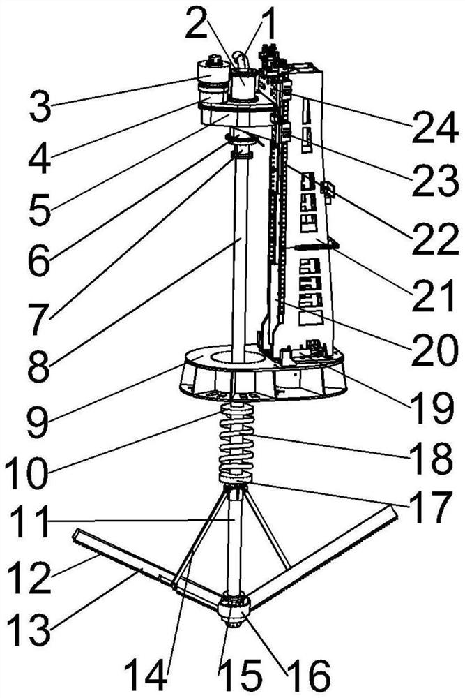
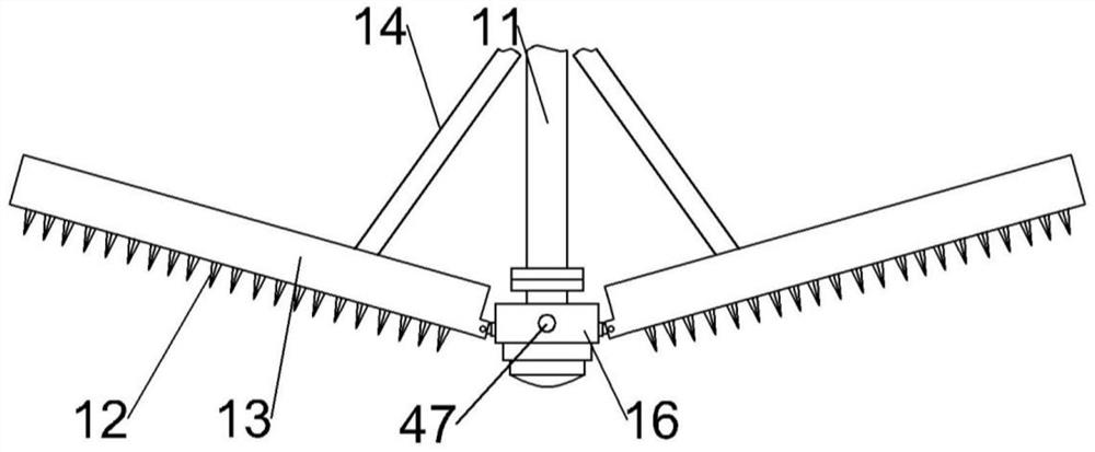
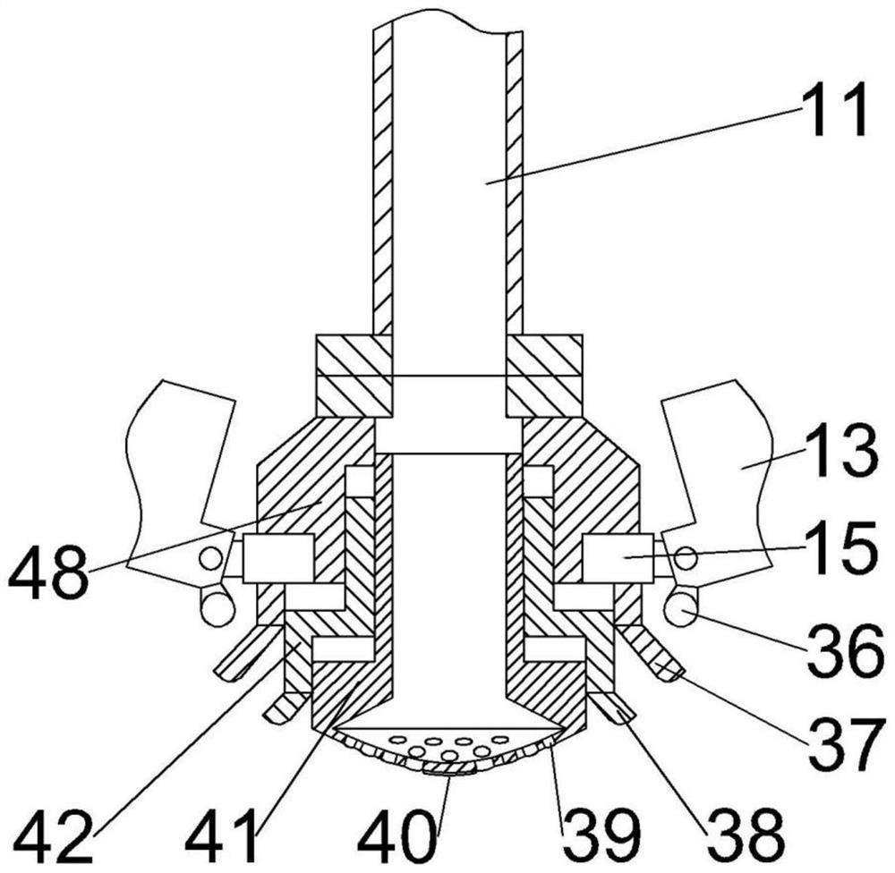
[0027] refer to Figure 1-8 As shown, the present invention provides a reactor catalyst automatic unloading equipment, including a column platform 9, a column assembly 21 is rotatably ...


PUM


Abstract

The invention belongs to the technical field of catalyst unloading equipment in the chemical industry, and particularly relates to reactor catalyst automatic unloading equipment which comprises a stand column platform, a stand column assembly is rotationally connected to one side of the top face of the stand column platform, and a motor reducer assembly is vertically and slidably connected to one side of the stand column assembly. A cutter row assembly used for cutting hardened catalysts is arranged below the motor speed reducer assembly, the top end of the cutter row assembly penetrates through the other side of the top face of the stand column platform and is in transmission connection with the lower portion of the motor speed reducer assembly, and a micro adjusting assembly used for finely adjusting the stand column assembly is arranged between the top face of the stand column platform and the bottom end of the stand column assembly. The bottom of the cutter row assembly is connected with a suction assembly used for collecting hardened catalysts, and an oil way brush ring used for controlling oil ways in the cutter row assembly and the micro adjusting assembly is arranged between the motor speed reducer assembly and the top end of the cutter row assembly. The device can improve the cleaning efficiency, reduce the labor intensity and uniformly crush the hardened catalyst.

Description

technical field [0001] The invention belongs to the technical field of catalyst unloading equipment in the chemical industry, in particular to an automatic catalyst unloading equipment for a reactor. Background technique [0002] In the process of petrochemical production, a large number of catalysts are used for the decomposition and refining of petroleum, and the production process uses a fixed bed reactor to load small particle catalysts. Such catalysts will deposit petroleum coke-like substances and a large amount of metal salts during use, resulting in the compaction of small particle catalysts. For some installations, the severely hardened catalyst requires a lot of labor and special equipment, the cleaning process takes a long time, and the operating environment contains polluted gas, and long-term operation is prone to safety hazards; during the cleaning process, a large amount of debris will remain, and Due to the uneven size of the broken debris, there will be a p...

Claims


Application Information

Patent Timeline
Patent Type & Authority Applications(China)
IPC IPC(8): B01J8/00B01J8/02B02C18/10B02C18/18B02C18/16B02C18/24
CPCB01J8/002B01J8/02B02C18/10B02C18/18B02C18/16B02C18/24Y02P20/584Y02E30/30
Inventor 项明龙陆晓峰姚晟朱晓磊李明轩郭豫鹏
Owner JIANGSU TIANPENG PETROCHEMICAL TECH CO LTD
Learn More