
Fixture for flaring test of alloy protective sleeve of railway through ground wire

A railway through ground wire and flaring test technology, which is applied to instruments, measuring devices, scientific instruments, etc., can solve the problems of difficulty in grasping the clamping force of the sheath tube, and achieve the effect of stable and good test and simple operation.

Pending Publication Date: 2022-05-20
TIANSHUI RAILWAY CABLE
View PDF0 Cites 0 Cited by
  • Summary
  • Abstract
  • Description
  • Claims
  • Application Information

AI Technical Summary

Problems solved by technology

[0003] In order to solve the problem that the clamping force of the sheath pipe is difficult to grasp, the invention proposes a jig for flaring tests on the alloy sheath pipe of the seamless environment-friendly railway through-earth wire

Method used


Image

  • Fixture for flaring test of alloy protective sleeve of railway through ground wire
  • Fixture for flaring test of alloy protective sleeve of railway through ground wire
  • Fixture for flaring test of alloy protective sleeve of railway through ground wire

Examples


Embodiment Construction

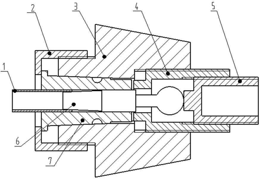
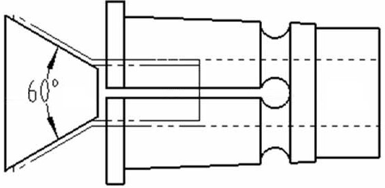
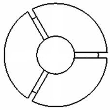
[0014] Below in conjunction with accompanying drawing, the present invention is further described: as figure 1 , the chuck 7 has a tapered surface on the outside, the chuck 7 is fixed in the fixed seat 3 through the taper surface, the pressure cap 2 and the fixed seat 3 are connected by threaded connection, the inner bottom wall of the pressure cap 2 presses the chuck 7, the chuck 7 produces deformation clamping alloy sheath 1 . The tightening length of the pressure cap 2 and the collet 7 can be controlled, so that the length of the collet 7 entering the fixed seat 3 is also controlled, so the clamping force of the collet 7 can be adjusted, and the alloy sheath is in contact with the inner hole wall of the collet The area is large, so a large clamping force can be obtained, and the alloy sheath is not easily deformed. The inner tip 6 is set in the chuck 7, and the inner wall of the alloy sheath 1 is pressed against the small taper surface of the inner tip 6. The guide shaft s...


PUM


Abstract

A fixing seat is provided with an inner hole, a chuck is fixed in the inner hole of the fixing seat in a conical surface fit mode, a pressing cap is connected and fastened with the fixing seat, the bottom wall in the pressing cap abuts against the chuck, the pressing cap is provided with a hole, and an axial through hole is formed in the chuck. The alloy sheath penetrates through the pressing cap to enter an axial through hole in the chuck, the inner center enters from the other end of the axial through hole and is sequentially provided with a taper face section, a guide shaft section and a tail section, the taper face section enters the alloy sheath, the taper face abuts against the inner wall of the alloy sheath, the guide shaft section is in sliding fit with the axial through hole of the chuck, and the tail section is located outside the axial through hole. The clamp has the beneficial effects that the clamp is used for clamping the alloy protective sleeve, the protective sleeve cannot deform, bend and slide due to clamping, the axis of the protective sleeve and the axis of the conical ejector core are always kept on the same straight line, the operation is simple and convenient, and the test is stable and good.

Description

technical field [0001] The invention relates to the field of wire and cable testing equipment, in particular to a jig for expanding the alloy sheath of a through-earth wire product used for high-speed railways. Background technique [0002] The high-speed railway environmental protection seamless metal through-ground wire is mainly laid on both sides of the railway line. It is a unified grounding cable for the entire line of the railway signal system, ensuring reliable protection for personnel and equipment, and at the same time providing a discharge channel for the overvoltage suffered by various equipment. The product has been working in a harsh environment for a long time and can withstand severe vibration. The outer sheath alloy tube flaring test of this product must meet the requirements of GB / T242-2007 standard and TB / T 3479-2017 "Railway Penetrating Ground Wire" 6.2.7 Outer sheath flaring test requirements in order to ensure the quality of the product and service lif...

Claims


Application Information

Patent Timeline
Patent Type & Authority Applications(China)
IPC IPC(8): G01N3/04
CPCG01N3/04G01N2203/04
Inventor 郭建力
Owner TIANSHUI RAILWAY CABLE
Learn More