Imprint roller and method for manufacturing same
A manufacturing method and technology of embossing rollers, applied in printing, printing devices, typewriters, etc., can solve problems such as lower rubber ratio, poor hardness between concave and convex parts, and breakage
- Summary
- Abstract
- Description
- Claims
- Application Information
AI Technical Summary
Problems solved by technology
Method used
Image
Examples
Embodiment 1
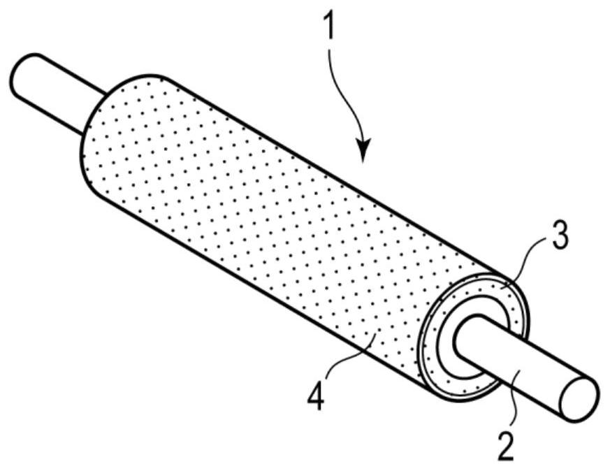
[0067] Primer No. 33 (manufactured by Shin-Etsu Chemical Co., Ltd.) was applied to the surface of the shaft body (diameter 5 mm×length 120 mm, SUS303).
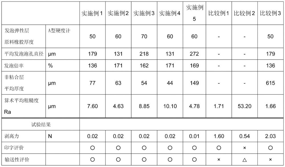
[0068] Next, the silicone rubber compound KE-904F-U (manufactured by Shin-Etsu Chemical Industry, hardness 45°, density 1.15) and KE-7170-U (manufactured by Shin-Etsu Chemical Industry, hardness 70°, density 1.18) were mixed at 80:20 Proportionally mixed to obtain a silicone rubber mixed compound (raw rubber: hardness 50°). 3 parts by weight of dicumyl peroxide as a vulcanizing agent, 0.5 parts by weight of finely pulverized AIBN (azobisisobutyronitrile) as a foaming agent, and 1 part by weight of iron oxide paste was mixed with an open mill to prepare a silicone rubber composition.
[0069] Next, the shaft body and the silicone rubber composition were integrally extruded using an extrusion molding machine, and the silicone rubber composition was molded into a cylindrical shape on the outer periphery of the shaft body.
[0...
Embodiment 2
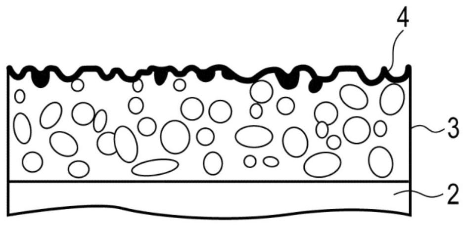
[0075] The foamed elastic layer was formed using the following silicone rubber composition, which was made of the same silicone rubber compound KE-904F-U as in Example 1 (manufactured by Shin-Etsu Chemical Co., Ltd., hardness 45°, density 1.15 ) and KE-7170-U (manufactured by Shin-Etsu Chemical Co., Ltd., hardness 70°, density 1.18) at a ratio of 40:60 to the silicone rubber mixed compound (raw rubber: hardness 60°), which is used as a foam An embossing roller was produced by the same method as in Example 1 except that the resin microspheres FN-100MD (manufactured by Matsumoto Yushi Pharmaceutical Co., Ltd.) of 1.5 parts by weight were used.
[0076] The foamed elastic layer of the obtained embossing roll had a foaming ratio of 171%, an average foamed cell diameter of 131 μm, an average thickness of the non-adhesive layer of 63 μm, and an arithmetic average roughness Ra of 4.63 μm.
Embodiment 3
[0078] The foamed elastic layer was formed using a silicone rubber composition obtained by adding 0.6 parts by weight of AIBN to 100 parts by weight of the same KE-7170-U (raw rubber: hardness 70°) as in Example 1. An embossing roll was produced by the same method as in Example 1 except that the average thickness of the non-adhesive layer was set to 54 μm.
[0079] The foamed elastic layer of the obtained embossing roller had an expansion ratio of 162%, an average foamed cell diameter of 218 μm, and an arithmetic average roughness Ra of 8.85 μm.
PUM
| Property | Measurement | Unit |
|---|---|---|
| surface roughness | aaaaa | aaaaa |
| thickness | aaaaa | aaaaa |
| diameter | aaaaa | aaaaa |
Abstract
Description
Claims
Application Information
 - R&D Engineer
- R&D Manager
- IP Professional
- Industry Leading Data Capabilities
- Powerful AI technology
- Patent DNA Extraction
Browse by: Latest US Patents, China's latest patents, Technical Efficacy Thesaurus, Application Domain, Technology Topic, Popular Technical Reports.
© 2024 PatSnap. All rights reserved.Legal|Privacy policy|Modern Slavery Act Transparency Statement|Sitemap|About US| Contact US: help@patsnap.com


