
Textile size stirring equipment for spinning

A technology for textile sizing and stirring equipment, which is used in mixer accessories, mixers, dissolving and other directions, can solve the problems of inability to mix textile sizing, unsatisfactory stirring effect, uneven stirring, etc., to reduce layering phenomenon and stirring effect. Good, improve the effect of stirring effect

Active Publication Date: 2022-05-20
HAIAN GUOYANG MACHINERY TECH CO LTD
View PDF8 Cites 0 Cited by
  • Summary
  • Abstract
  • Description
  • Claims
  • Application Information

AI Technical Summary

Problems solved by technology

Polymers will be produced during stirring and these polymers are easy to sink to the bottom. In the process of stirring, the existing stirring equipment does not stir the polymer or high-concentration bottom-sinking slurry uniformly, and the stirring effect is not ideal. Make the layered textile slurry mix together, the mixing effect is poor

Method used


Image

  • Textile size stirring equipment for spinning
  • Textile size stirring equipment for spinning
  • Textile size stirring equipment for spinning

Examples


Embodiment 1

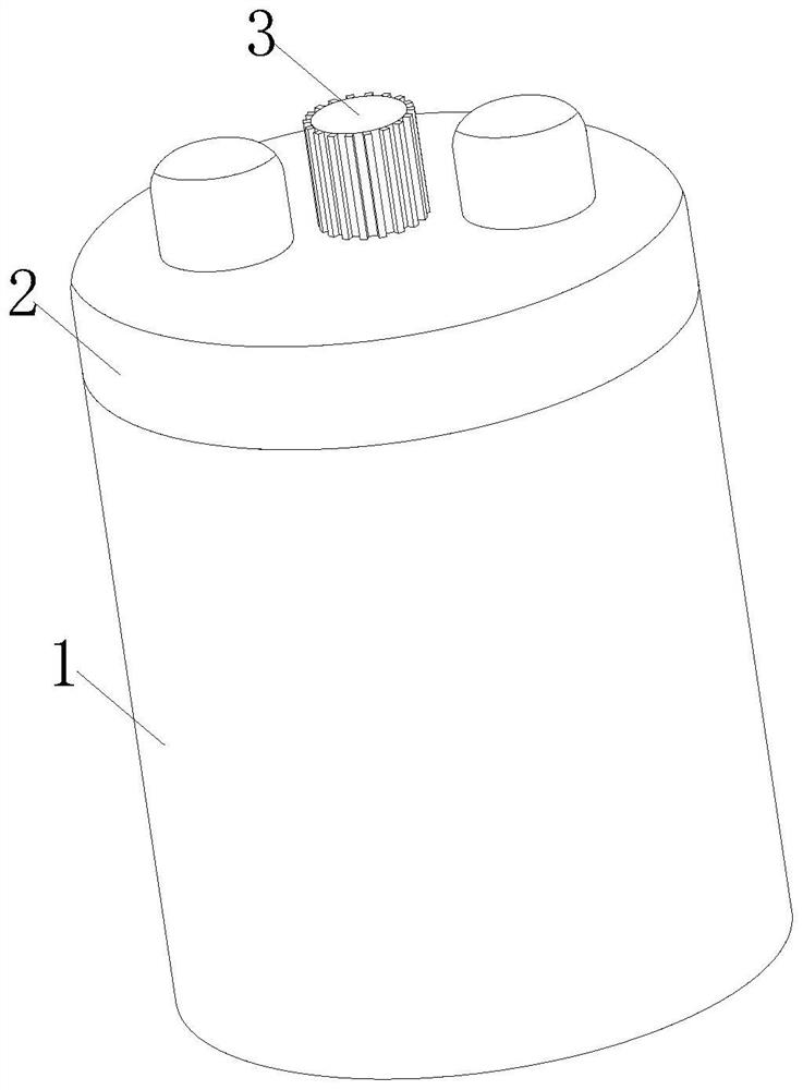
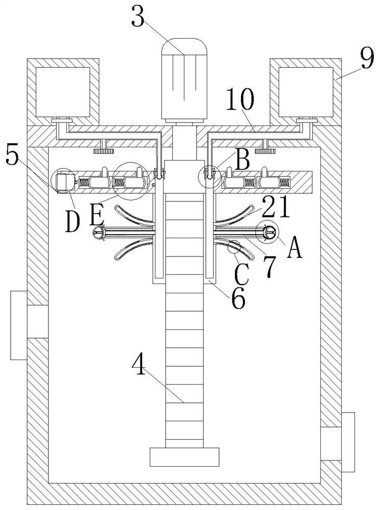
[0030] as Figures 1 through 6As shown, an embodiment of the present invention is a textile slurry stirring apparatus for textiles, comprising a housing 1, the top surface of the housing 1 is close to the edge position threaded connected to the cover 2, the top surface of the cover 2 is fixed near the middle position is fixed with a motor 3, the output shaft of the motor 3 is fixed connected to the rotary rod 4, one end of the rotary rod 4 extends to the interior of the housing 1, the outer surface of the rotary rod 4 is threaded with a stirring plate 5. When working, by setting the housing 1, the staff first through the inlet to the inside of the shell 1 to add textile slurry, when the addition is not completed, the control system controls the motor 3 forward rotation, because the mixing plate 5 and the rotary rod 4 thread connection, at this time, the stirring plate 5 rotates down inside the shell 1, the textile slurry inside the shell 1 is stirred downwards, reducing the delamin...

Embodiment 2

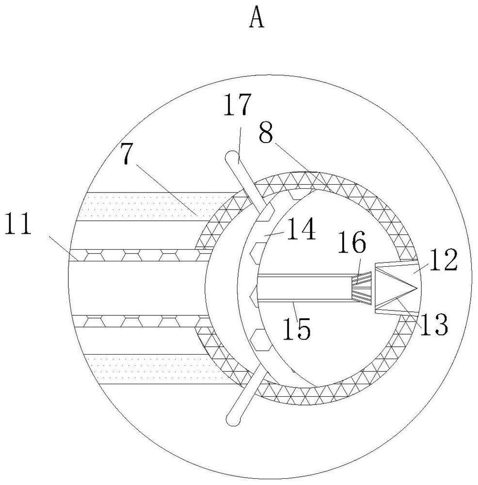
[0040] as Figure 7As shown, compared with example one, wherein another embodiment of the present invention is: the stirring plate 5 is provided with a uniformly distributed mounting groove 28, the inner surface of the mounting groove 28 is fixed in one side near the intermediate position is fixed with a spring 29, one end of the spring 29 is fixed with a second airbag 30, the top surface of the second airbag 30 is close to the edge of the side of the position through which the ejector rod 31 is connected, the ejector rod 31 is connected to the stirring plate 5 through the activity connection. When working, the present invention by setting the mounting tank 28, in the process of rotation of the stirring plate 5, the centrifugal force when the water inside the second airbag 30 moves away from the direction of the rotary rod 4, i.e., to overcome the elastic force of the spring 29 in the direction of the installation slot 28 to move away from the direction of the rotary rod 4, i.e., t...


PUM


Abstract

The invention belongs to the technical field of spinning, and particularly relates to spinning slurry stirring equipment for spinning, which comprises a shell, a cover body is in threaded connection with the top surface of the shell close to the edge position, a motor is fixedly mounted on the top surface of the cover body close to the middle position, and an output shaft of the motor is fixedly connected with a rotating rod; one end of the rotating rod extends into the shell, and the outer surface of the rotating rod is in threaded connection with a stirring plate. By arranging the shell, the problems that in the prior art, in the spinning production process, polymers can be generated in the stirring process, the polymers are likely to sink to the bottom, and in the stirring process, existing stirring equipment is not uniform in stirring of the polymers sinking to the bottom or high-concentration slurry sinking to the bottom, and the stirring effect is not ideal are solved; the layered textile size can be mixed together, the stirring effect is good, the layering phenomenon of the textile size is reduced, and the stirring effect is guaranteed.

Description

Technical field [0001] The present invention belongs to the field of textile technology, specifically a textile slurry stirring equipment for textiles. Background [0002] Textile slurry mixer is mainly used for the textile fabric production of slurry with slurry to stir the equipment evenly, by pouring the textile slurry raw materials into the inside of the mixing drum, and then through the shaft for high-speed mixing, so that the textile slurry raw materials can be evenly mixed, so as to facilitate the textile fiber and other scattered textile materials to be glued to the synthetic cloth; [0003] In the existing textile production process, the textile slurry is stirred in the mixing tank, and the stirred slurry directly affects the quality of the textile. Polymers will be generated in the stirring and these polymers are easy to sink, and in the mixing process, the existing stirring equipment is unevenly stirred on the sinking polymer or high concentration of the bottom slurry,...

Claims


Application Information

Patent Timeline
Patent Type & Authority Applications(China)
IPC IPC(8): B01F31/44B01F35/30B01F35/33
Inventor 王昌国
Owner HAIAN GUOYANG MACHINERY TECH CO LTD
Learn More