
Forward and reverse bidirectional inclined shaft special drilling machine mechanism based on sliding guide mechanism

A sliding steerable, inclined well technology, applied in directional drilling, drill pipe, drill pipe, etc., can solve the problems of high labor intensity, low construction efficiency, high price, etc., to reduce transportation and maintenance costs, simplify calling and The effect of replacement and improvement of quality

Inactive Publication Date: 2022-05-17
江苏昭旸智能装备有限公司
View PDF0 Cites 0 Cited by
  • Summary
  • Abstract
  • Description
  • Claims
  • Application Information

AI Technical Summary

Problems solved by technology

[0003] The tank-climbing method was the first to be used to construct the guide wells for the pressure pipeline shafts and inclined wells of the pumped storage power station, which has the disadvantages of dangerous working environment, high labor intensity of the staff, and serious occupational injuries. Low, gradually replaced by raise drilling method
However, the drilling devices developed by relevant domestic research institutes and drilling companies in construction projects such as vertical shafts, inclined shafts, and raise drilling are all single-function products.
As a result, when complex engineering problems are encountered, it is necessary to continuously call and replace drilling rigs, and the transportation and maintenance costs of drilling equipment are high and expensive

Method used


Image

  • Forward and reverse bidirectional inclined shaft special drilling machine mechanism based on sliding guide mechanism
  • Forward and reverse bidirectional inclined shaft special drilling machine mechanism based on sliding guide mechanism
  • Forward and reverse bidirectional inclined shaft special drilling machine mechanism based on sliding guide mechanism

Examples


Embodiment Construction

[0022] The following will clearly and completely describe the technical solutions in the embodiments of the present invention with reference to the accompanying drawings in the embodiments of the present invention. Obviously, the described embodiments are only some, not all, embodiments of the present invention. Based on the embodiments of the present invention, all other embodiments obtained by persons of ordinary skill in the art without making creative efforts belong to the protection scope of the present invention.

[0023] The embodiment of the special drilling rig mechanism for forward and reverse bidirectional inclined wells based on the sliding steering mechanism is as follows:

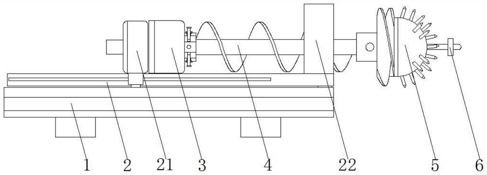
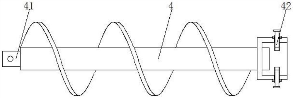
[0024] see Figure 1-Figure 5 , a special drilling rig mechanism for forward and reverse bi-directional inclined wells based on a sliding guide mechanism, including a frame 1, the surface of the frame 1 is rotatably connected with a cover support plate 2, which is used for the cover support of...


PUM


Abstract

The invention provides a forward and reverse bidirectional inclined shaft special drilling machine mechanism based on a sliding guide mechanism. The forward and reverse bidirectional inclined shaft special drilling machine mechanism based on the sliding guide mechanism comprises a rack, a shield supporting plate is rotationally connected to the surface of the rack, a rotating machine base is arranged between the surface of the lower end of the shield supporting plate and the rack, and a hydraulic transmission shaft is arranged on the lower surface of a sliding guide seat; according to the drilling machine mechanism special for the forward and reverse two-way inclined shaft based on the sliding guide mechanism, a transverse hydraulic rod and a direction adjusting hydraulic rod in the direction adjusting mechanism are used in cooperation with a shield supporting plate, and multi-angle adjustment can be conducted on the spiral drill rod and a composite tower-shaped drill bit; therefore, drilling operation of a vertical shaft, an inclined shaft and a raise well is achieved, calling and replacing of the drilling machine are simplified, the transportation and maintenance cost can be reduced, and meanwhile through cooperation of the spiral drilling rod and the composite tower-shaped drill bit, integrated operation of cutting and loading can be achieved.

Description

technical field [0001] The invention relates to the technical field of drilling for pumped storage power stations, in particular to a special drilling mechanism for forward and reverse bidirectional inclined wells based on a sliding guide mechanism. Background technique [0002] The construction of large-scale pumped storage power stations mainly relies on the height difference characteristics of the upper and lower reservoirs in mountainous terrain to convert water into gravitational potential energy or electrical energy. The structures of a pumped storage power station generally include upper and lower reservoirs and pressure pipelines. Among them, the upper reservoir is built in the upper part of the mountain, the lower reservoir is arranged in the lower part of the mountain, and the pressure pipeline is built inside the mountain. As the installed capacity of pumped storage power stations increases, the power generation water level of the water delivery system increases,...

Claims


Application Information

Patent Timeline
IPC IPC(8): E21B7/04E21B15/04E21B15/00E21B17/22E21B10/43E21B17/03E21B17/046
CPCE21B7/04E21B15/04E21B15/045E21B15/003E21B17/22E21B10/43E21B17/03E21B17/046Y02E60/16
Inventor 张基伟刘志强丁扬扬窦斌
Owner 江苏昭旸智能装备有限公司
Learn More