
Steel structure fabricated building

A prefabricated, steel structure technology, applied in buildings, protected buildings/shelters, building components, etc., can solve the waste of wall panels, the lifting of the weight of wall trusses, and the connection between wall trusses and vertical support rods. concave inequality problem

Pending Publication Date: 2022-05-17
SHENZHEN JINXIN GREEN CONSTR LTD BY SHARE LTD
View PDF8 Cites 0 Cited by
  • Summary
  • Abstract
  • Description
  • Claims
  • Application Information

AI Technical Summary

Problems solved by technology

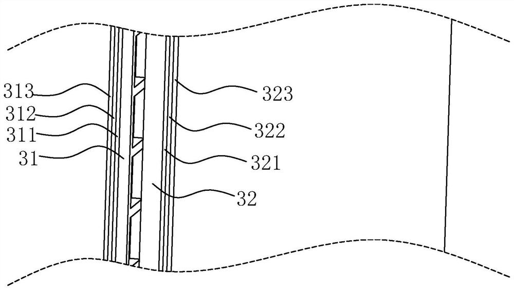
[0004] In this installation method, because the main function of the wall truss is not load-bearing, the thickness between the two parallel sides of the wall truss that are close to two adjacent spaces is generally not as thick as that of the vertical support rods in the same direction. , and at this time, it is easy to appear concave and uneven at the connection between the wall truss and the vertical support rod. If this situation is to be avoided at this time, it is necessary to attach several layers of wall panels to the wall in the concave place. If the wall truss is made to be the same thickness as the vertical support bar, the weight of the wall truss will be greatly increased, which is not conducive to the movement on site, so it needs to be improved

Method used


Image

  • Steel structure fabricated building
  • Steel structure fabricated building
  • Steel structure fabricated building

Examples


Embodiment 1

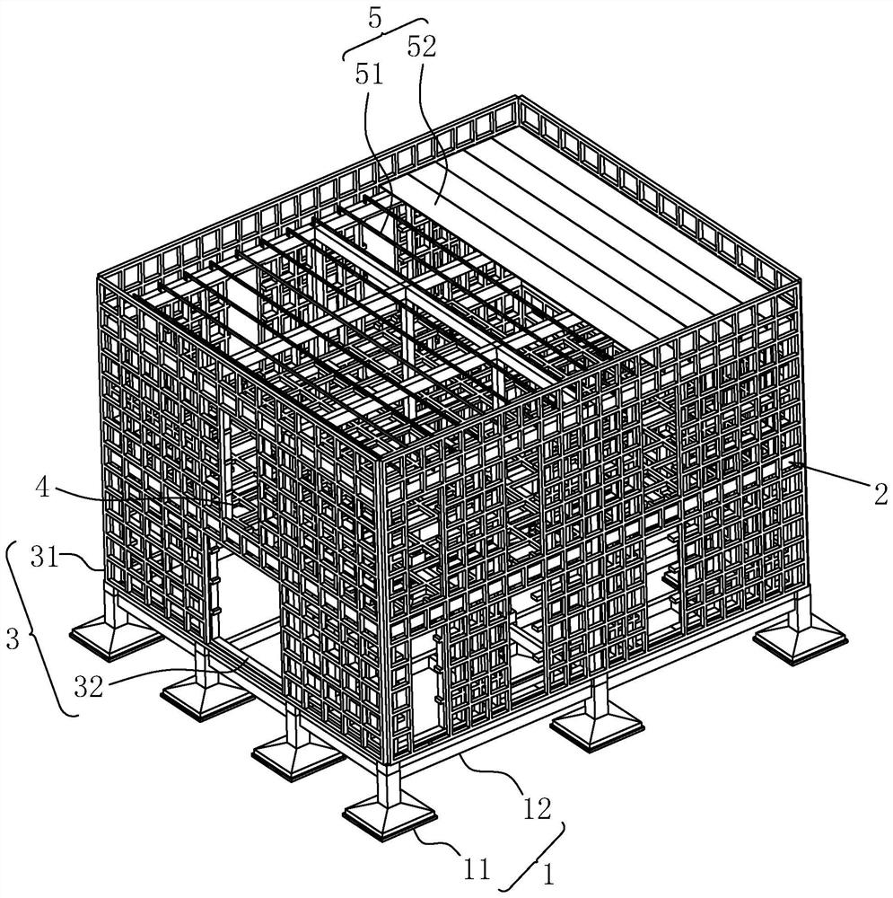
[0036] Embodiment 1, with reference to figure 1 , a prefabricated steel structure building, comprising a base structure 1, a main steel frame 2, a wall truss 3, a floor truss 4 and a roof structure 5, the base structure 1 is arranged under the main steel frame 2, and the wall truss 3 is vertically It is installed in the main frame to cooperate with the main steel frame 2 to divide the outdoor space and the indoor space. The floor truss 4 is horizontally installed inside the main steel frame 2 to divide the inside of the main steel frame 2 into upper and lower floors. The roof structure 5 is set The upper end of the main steel frame 2 is used to cap the upper end of the main steel frame 2 .

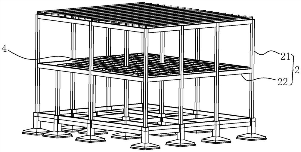
[0037] refer to figure 2 , the main steel frame 2 includes a plurality of vertical support rods 21 and a plurality of horizontal support rods 22, the vertical support rods 21 are square steel structures, the horizontal support rods 22 are I-shaped steel structures, and the two ends of th...

Embodiment 2

[0048] Embodiment two, refer to Figure 4 and Figure 5 , the difference from Embodiment 1 is that the base ring beam 12 is provided with a moving part 121 at a position opposite to the independent foundation 11 up and down for driving the base ring beam 12 to move horizontally, so that the distance between the base ring beam 12 and the independent foundation 11 The connection between them is no longer a fixed connection, but the foundation ring beam 12 can move horizontally on the independent foundation 11. At this time, the foundation ring beam 12 and the part above the foundation ring beam 12 will be changed when the position needs to change. It is more convenient, and it is no longer necessary to move by means of demolition.

[0049] refer to Figure 4 and Figure 5 The moving part 121 includes a support block 1211 and a roller 1212. The support block 1211 is in the shape of a cuboid and is made of concrete. The upper end of the support block 1211 is fixedly connected w...


PUM


Abstract

The invention discloses a steel structure fabricated building which comprises a main body steel frame and two wall surface trusses, the main body steel frame comprises a plurality of vertical supporting rods, the two wall surface trusses are vertically parallel to each other, and the two wall surface trusses are defined as an inner wall truss and an outer wall truss respectively; the vertical supporting rods are located between the inner wall truss and the outer wall truss and fixedly connected with the inner wall truss and the outer wall truss correspondingly, the overall installation efficiency and installation precision of the building can be improved, and follow-up disassembly is also facilitated.

Description

technical field [0001] The invention relates to the field of steel structure buildings, in particular to a steel structure assembled building. Background technique [0002] Steel structure buildings have been more and more accepted by people because of their high structural strength, good earthquake resistance, and the reusable properties of steel. [0003] A common steel structure building includes a main steel frame and a wall truss vertically installed on the main steel frame. The horizontal support rods are built between the vertical support rods and the horizontal support rods to form the general frame of the steel structure building; the wall trusses are specifically installed between two adjacent vertical support rods, and the wall trusses The two vertical side surfaces of the two adjacent vertical support rods are respectively abutted against the two side surfaces that are close to each other. [0004] In this installation method, because the main function of the w...

Claims


Application Information

Patent Timeline
Patent Type & Authority Applications(China)
IPC IPC(8): E04B1/00E04B1/24E04B2/58E04B1/58E04B1/66E04B1/343E04B1/98E04H9/02
CPCE04B1/00E04B1/24E04B2/58E04B1/2403E04B1/66E04B1/0007E04B1/34336E04B1/34352E04B1/98E04H9/021E04B2001/2463
Inventor 张枫赵沙毛华渊
Owner SHENZHEN JINXIN GREEN CONSTR LTD BY SHARE LTD
Learn More