Lidar system for wind measurement

A technology of lidar, wind power, applied in the field of measurement process

Pending Publication Date: 2022-05-13
国家航空航天研究所
View PDF0 Cites 0 Cited by
  • Summary
  • Abstract
  • Description
  • Claims
  • Application Information

AI Technical Summary

Problems solved by technology

But because the base measurements thus combined are derived from mutually independent signals, the CNR_sp ratio of the averaged result is again only increased by N 1 / 2 times

Method used


Image

  • Lidar system for wind measurement
  • Lidar system for wind measurement
  • Lidar system for wind measurement

Examples


Embodiment Construction

[0053] For the sake of clarity, the dimensions of elements shown in these figures do not correspond to real sizes or real size ratios. Furthermore, some of these elements are shown only symbolically, and the same references indicated in different figures designate the same or elements with the same function.

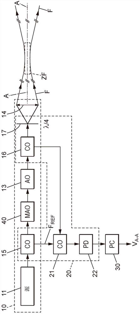
[0054] figure 1 The lidar system according to the invention shown in may consist of a continuous emission lidar system. It includes a laser emission source 10 , a heterodyne detection system 20 and a Doppler calculation module 30 .

[0055] The laser emitting source 10 may include an initial laser source 11 (labeled source), an optical amplifier 13 (labeled AO), and an optical outlet 14 . The laser emission source 10 is therefore designed to generate a laser beam F with a converging beam structure in the spatial region behind the optical outlet 14 . In this way, the transverse cross-section of the beam F with the optical axis A-A decreases between the optical exit 14 ...


PUM


Abstract

A lidar system adapted to perform a wind measurement related to a focal zone (ZF) of a laser beam (F) emitted by the system. The system comprises time control means (40) for the laser beam adapted to place this laser beam in the form of successive laser pulses such that each laser pulse has a single length greater than or equal to twice the Rayleigh length (lR) divided by the propagation velocity of the laser pulse in the atmosphere and less than 20 [mu] s. Advantageously, the individual length of each laser pulse is between 0.2 and 5 times the coherence time of the effective atmosphere in the focal region. The lidar system provides a better spectral CNR ratio at an equivalent spatial resolution than the spectral CNR ratio of a system at a current technology development level.

Description

technical field [0001] This specification relates to a Lidar (LIDAR) system suitable for performing anemometric measurements, and a measurement process using this system. Background technique [0002] LiDAR systems, or "Light Detection and Ranging", are well known and used in many applications, in particular for making anemometric measurements. For anemometric velocity measurements, the laser beam is backscattered by particles suspended in the air (such as aerosols or solid particles) and carried by the air flow. Next, the component of the wind speed parallel to the laser beam is inferred from the frequency shift due to the Doppler effect. However, several reasons limit the performance of existing lidar systems for anemometric velocity measurements. Among these reasons, one of the biggest constraints is the small value of the CNR spectral ratio (representing the spectral "carrier-to-noise ratio"), which is written as the CNR_sp ratio and is the ratio of the maximum amplitu...

Claims


Application Information

Patent Timeline
Patent Type & Authority Applications(China)
IPC IPC(8): G01S17/58G01S17/88G01S17/95G01S7/484G01S7/487G01S7/4911G01S7/493
CPCG01S17/58G01S17/88G01S17/95G01S7/484G01S7/4876G01S7/4911G01S7/493Y02A90/10G01S7/4808
Inventor 戴维德·托姆林·米切尔贝阿特里塞·奥盖雷马西厄·瓦拉
Owner 国家航空航天研究所
Why Eureka
Try Eureka