
Encryption valve

A valve body and valve cover technology, applied in valve details, valve device, valve shell structure, etc., can solve problems such as affecting service life, affecting production speed, malicious damage, etc., to extend service life, improve production efficiency, and improve assembly. effect of speed

Pending Publication Date: 2022-05-13
TIANHONG VALVE TECH QUANZHOU CO LTD
View PDF1 Cites 0 Cited by
  • Summary
  • Abstract
  • Description
  • Claims
  • Application Information

AI Technical Summary

Problems solved by technology

[0004] However, the valve with magnetic lock also has certain shortcomings:
[0005] 1. The lock cap is connected to the valve stem through a pin, and the connection is located at an obvious position outside the valve, which is easy to be maliciously damaged by people, or corroded by rainwater, which will affect the service life
[0006] 2. In order for the pin to connect the valve stem to the lock cap, it is necessary to drill holes on the outside of the lock cap to position the pin during processing, which makes the processing and assembly of the valve cumbersome and affects the production speed
[0007] 3. Punching holes will cause trauma to the lock cap and valve stem, and the pins, as connectors and limiters, will be subjected to forces from all directions at the same time, which will affect the service life of the valve

Method used


Image

  • Encryption valve
  • Encryption valve
  • Encryption valve

Examples


Embodiment Construction

[0035] The specific embodiments of the present invention will be further described below in conjunction with the accompanying drawings and examples. The following examples are only used to illustrate the technical solutions of the present invention more clearly, but not to limit the protection scope of the present invention.

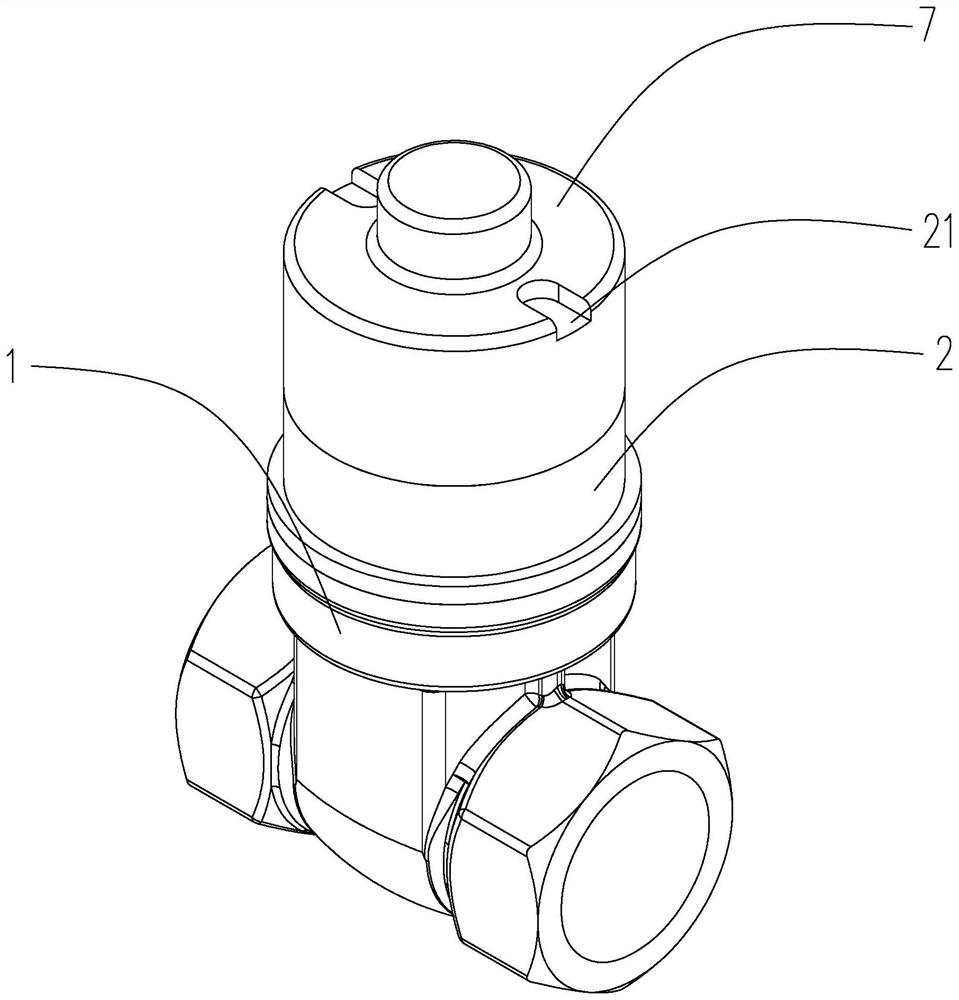
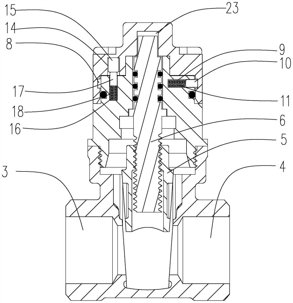
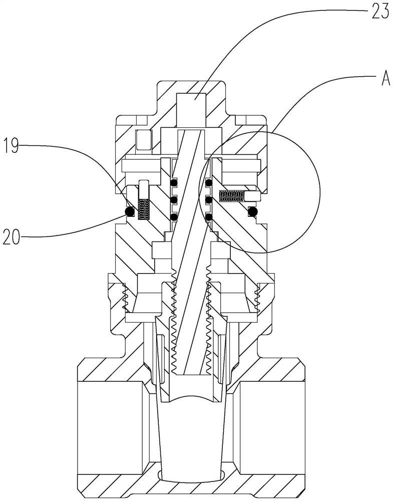
[0036] Such as Figure 1-Figure 5 As shown, an encryption valve includes a valve body 1, a valve cover 2 arranged on the valve body 1, a water inlet channel 3 and an outlet water channel 4 opened in the valve body 1, and a water inlet channel 3 arranged on the valve body 1. The opening and closing member 5 used to control the opening and closing of the fluid between the water outlet channel 4, one end is arranged in the valve body 1, and the valve stem 6 connected to the opening and closing member 5 and one end passes through the valve body 1 and the valve cover 2 is arranged on the valve body 1. On the valve cover 2 and the inner side is against the top...


PUM


Abstract

The invention provides an encryption valve which is simple in structure and capable of hiding a magnetic locking device and does not leave marks on an external display part. Comprising a valve body, a valve cover arranged on the valve body, a water inlet channel and a water outlet channel formed in the valve body, an opening and closing piece arranged between the water inlet channel and the water outlet channel and used for controlling opening and closing of fluid, and a valve rod with one end arranged in the valve body, connected to the opening and closing piece and the other end penetrating out of the valve body and the valve cover. The sealing cover is arranged on the valve cover, the inner side of the sealing cover abuts against the top face of the valve cover and used for isolating the valve rod from the external space, and the circumferential limiting device is arranged between the sealing cover and the valve rod and used for driving the valve rod to rotate when the sealing cover rotates. A magnetic locking device used for preventing the valve rod from rotating due to the fact that the encryption cover is rotated by other people is further arranged between the encryption cover and the valve cover, and an axial limiting device used for fixing the encryption cover to the valve cover is further arranged between the encryption cover and the valve cover.

Description

technical field [0001] The invention belongs to the technical field of valves, in particular to an encryption valve. Background technique [0002] Magnetic lock valves are widely used in pipeline transportation to prevent the valve from being opened and closed arbitrarily. Magnetic lock valves are usually equipped with several magnetic points on the parts that pull the valve switch connection point. Only the use of magnetic points The corresponding key can turn the valve, otherwise it will not be able to open and close. [0003] The most common magnetic lock valve structure on the market is a valve with a magnetic lock disclosed in a Chinese patent [application number: 200920313315.6], which includes a valve body, a bonnet and a hand wheel. Valve stem, one end of the valve stem is connected with the valve core, and the other end passes through the bonnet and is fixedly connected with a lock cap. The bottom surface of the lock cap is close to the top surface of the bonnet. ...

Claims


Application Information

Patent Timeline
Patent Type & Authority Applications(China)
IPC IPC(8): F16K35/16F16K35/02F16K27/00F16K27/08
CPCF16K35/16F16K35/025F16K27/00F16K27/08
Inventor 洪晓亮洪海波卓思庆卓友钦
Owner TIANHONG VALVE TECH QUANZHOU CO LTD
Learn More