
Bearing unit

A bearing and bearing ring technology, applied in bearing components, bearings, roller bearings, etc., can solve problems such as cost increase, achieve the effect of offsetting lubricant loss, preventing pollutants from infiltrating into rolling space, and effectively assembling

Pending Publication Date: 2022-05-13
AB SKF +1
View PDF0 Cites 0 Cited by
  • Summary
  • Abstract
  • Description
  • Claims
  • Application Information

AI Technical Summary

Problems solved by technology

This can result in bearing units having to be replaced or reworked several times within the wheel's scheduled maintenance intervals, whereby the cost of maintenance work can increase due to increased material and / or labor charges

Method used


Image

  • Bearing unit

Examples


Embodiment Construction

[0019] In the following, identical or functionally equivalent elements are designated by the same reference numerals.

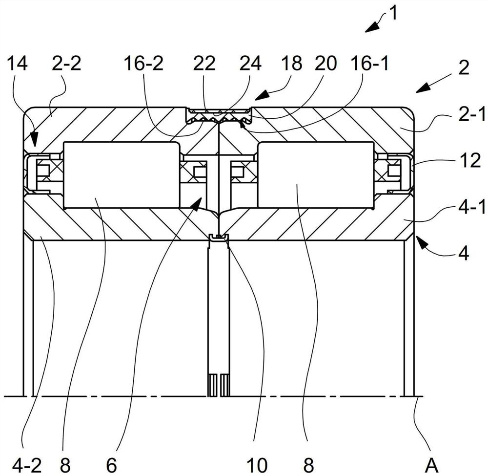
[0020] figure 1 A bearing unit 1 comprising an outer ring 2 and an inner ring 4 is shown. The outer ring 2 comprises a first bearing ring part 2-1 and a second bearing ring part 2-2. The inner ring 4 also includes a first bearing ring part 4-1 and a second bearing ring part 4-2. The outer ring 2 and the inner ring 4 are rotatable relative to each other and define between them a rolling space 6 in which a plurality of rolling elements 8 are arranged which enable the outer ring 2 and the inner ring 4 to be opposed relative to each other rotate. exist figure 1 In the bearing unit 1, the rolling elements 8 are formed as cylindrical rollers. However, other types of rolling elements may also be used, such as balls, tapered rollers, etc.

[0021] In the exemplary embodiment shown, the two bearing ring parts 4-1, 4-2 of the inner ring 4 are connected via a clam...


PUM


Abstract

Disclosed is a bearing unit (1), in particular for a wheel of a rail vehicle, comprising a first bearing ring (2) and a second bearing ring (4), the first bearing ring (2) and the second bearing ring (4) being rotatable relative to each other and defining a rolling space (6) therebetween, in which a plurality of rolling elements (8) are arranged, the rolling elements (8) enable the first bearing ring (2) and the second bearing ring (4) to rotate relative to each other, the first and / or the second bearing ring (2, 4) being configured in two parts and comprising a first bearing ring part (2-1, 4-1) and a second bearing ring part (2-2, 4-2), the first bearing ring part (2-1, 4-1) and the second bearing ring part (2-2, 4-2) being connected by a connecting element (18), wherein the first and the second bearing ring part (2-1, 4-1, 2-2, 4-2) are at least partially adjacent to each other in the axial direction.

Description

technical field [0001] The invention relates to a bearing unit according to the preamble of patent claim 1 . Background technique [0002] When a wheel on a train is removed, for example for maintenance or repair, the bearing unit which mounts the wheel on the axle is usually also removed. What can happen here is that when the wheel is removed, the bearing unit may not be removed without damage, so the bearing unit has to be reworked or even replaced before the wheel can be reinstalled. For example, during disassembly, external contaminants such as dust particles, etc. may penetrate into the bearing and / or lubricant may escape from the bearing. Bearing parts can also be damaged when the wheel is removed. This may result in the bearing unit having to be replaced or reworked several times within the wheel's scheduled maintenance intervals, whereby the cost of the maintenance work may increase due to increased material and / or labor costs. Contents of the invention [0003]...

Claims


Application Information

Patent Timeline
IPC IPC(8): F16C33/60F16C33/78F16C19/22B60B27/00
CPCF16C33/60F16C33/783F16C33/7826F16C19/22B60B27/001B60B27/0073F16C2326/02F16C19/28F16C19/225F16C33/4605F16C33/585F16C33/586F16C43/04F16C2208/66F16C2208/12F16C2226/74F16C2326/10F16C33/768F16C41/04
Inventor J.阿斯曼X.程P.米尼O.诺沃特尼
Owner AB SKF
Learn More