Compressed air energy storage system and control method thereof

A compressed air energy storage and control valve technology, which is applied in steam engine devices, liquid variable displacement machines, machines/engines, etc., can solve the problems of waste of heat energy, waste of cold energy, poor temperature followability, etc., and achieve good followability , Improve heat exchange efficiency, improve the effect of heat exchange matching degree

Active Publication Date: 2022-05-13
XI AN JIAOTONG UNIV
View PDF14 Cites 1 Cited by
  • Summary
  • Abstract
  • Description
  • Claims
  • Application Information

AI Technical Summary

Problems solved by technology

Because compressed air energy storage technology will generate a lot of waste heat in the compressed air stage, resulting in waste of heat energy
Moreover, due to the heat transfer loss, the air temperature at the outlet of the expander is lower than the ambient temperature during the energy release process, which also leads to waste of cooling energy
In the prior art, Chinese patent CN105569753A has disclosed a power generation device that utilizes the Organic Rankine Cycle (ORC) to recycle waste heat and cold energy, but in the Organic Rankine Cycle (ORC) system, the heat exchange stage between the organic working fluid and the heat source , the temperature following is not good, so there is a very large loss

Method used


Image

  • Compressed air energy storage system and control method thereof

Examples


Embodiment Construction

[0022] The present invention will be described in further detail below in conjunction with the accompanying drawings.

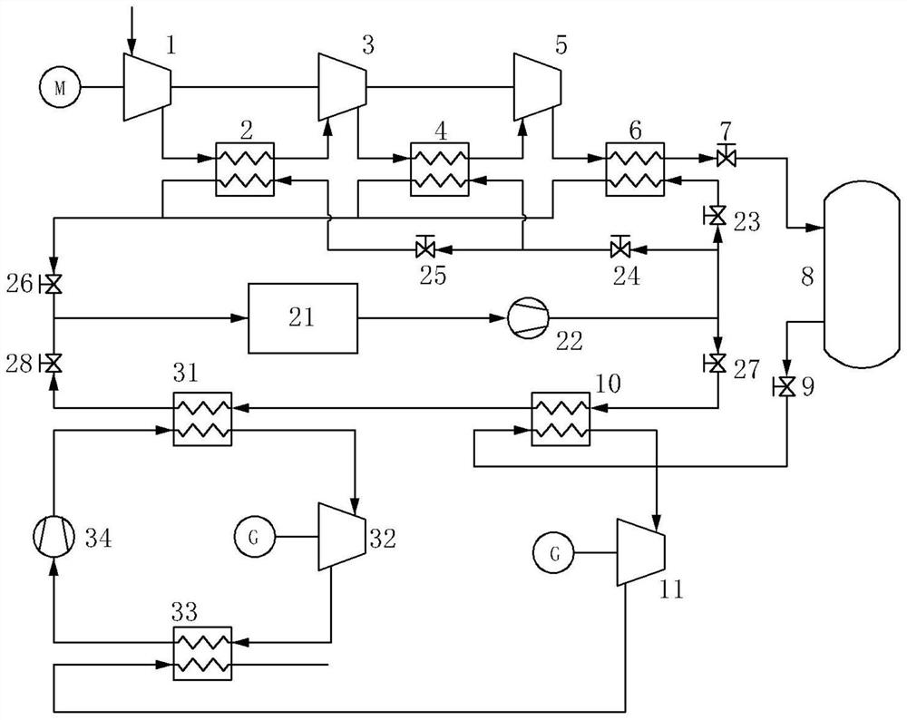
[0023] see figure 1 , a compressed air energy storage system of the present invention, the main structure includes an electric energy storage system, a thermal energy storage and release system, an electric energy release system and a triangular flash cycle system.

[0024] Among them, the electric energy storage system includes a compressor, an interstage cooler and a high-pressure gas storage tank 8, the compressor is driven by an electric motor, and low-cost electric energy drives the electric motor, and the exhaust port of the compressor is connected to the hot side inlet of the interstage cooler , the hot side outlet of the interstage cooler is connected to the high-pressure gas storage tank 8 . During the working process of the compressor, the air is compressed to a state of high temperature and high pressure, and then through the cooling effect of the...


PUM


Abstract

The invention discloses a compressed air energy storage system and a control method thereof. The compressed air energy storage system comprises an electric energy storage system, a heat energy storage and release system, an electric energy release system and a triangular flash evaporation circulation system, the electric energy storage system comprises a compressor, an interstage cooler and a high-pressure gas storage tank, the compressor is driven by a motor, an exhaust port of the compressor is connected with a hot side inlet of the interstage cooler, and a hot side outlet of the interstage cooler is connected with the high-pressure gas storage tank; the heat energy storage and release system comprises a heat storage tank and a first working medium pump; the electric energy release system comprises a first heat exchanger and an expansion machine; the expansion machine is connected with a high-pressure gas storage tank through the first heat exchanger; the triangular flash evaporation circulation system comprises a second heat exchanger, a two-phase expansion machine, a condenser and a second working medium pump, and exhaust gas generated after the expansion machine works is introduced into the condenser. A heat source of the triangular flash evaporation circulating system comes from a heat storage working medium of the heat storage tank, a cold source comes from cold exhaust gas after acting in the expansion machine in the energy release stage of the electric energy release system, and the triangular flash evaporation circulating system has high heat exchange efficiency.

Description

technical field [0001] The invention relates to the technical field of energy storage, in particular to a compressed air energy storage system and a control method thereof. Background technique [0002] Compressed air energy storage system is an electric energy storage system with large storage capacity, high operating efficiency, long service life and low operating cost. Its main working principle is: during the period of low power consumption, use the surplus low-cost electric energy to drive the compressor, compress the air into the gas storage device and store it; and during the peak period of power consumption, release the compressed air from the gas storage device , and then the high-pressure air drives the expander to do work and output high-quality electric energy. Because the compressed air energy storage technology will generate a lot of waste heat in the compressed air stage, resulting in waste of heat energy. Moreover, due to the heat transfer loss, the air tem...

Claims


Application Information

Patent Timeline
Patent Type & Authority Applications(China)
IPC IPC(8): F01K13/00F01K13/02F01K25/08F01K7/00F04B37/12
CPCF01K13/00F01K13/02F01K25/08F01K7/00F04B37/12Y02E60/16
Inventor 吴伟烽李晓然李程翊张寅
Owner XI AN JIAOTONG UNIV
Why Eureka
Try Eureka