
Self-locking elastic clamping device capable of freely combining rotation

An elastic clamping and self-locking technology, applied in positioning devices, clamping, manufacturing tools, etc., can solve problems such as low operating efficiency, inability to clamp and position workpieces, etc., to improve work efficiency, facilitate disassembly and assembly, and accurately and quickly clamp The effect of tight positioning

Pending Publication Date: 2022-05-13
铜陵福茂再生资源利用有限公司 +1
View PDF5 Cites 0 Cited by
  • Summary
  • Abstract
  • Description
  • Claims
  • Application Information

AI Technical Summary

Problems solved by technology

[0003] Invention The purpose of the present invention is to address the above deficiencies and provide a self-locking elastic clamping device that freely combines and rotates to solve the problem that the existing common clamps have low operating efficiency and cannot clamp and position the workpiece accurately and quickly.

Method used


Image

  • Self-locking elastic clamping device capable of freely combining rotation
  • Self-locking elastic clamping device capable of freely combining rotation
  • Self-locking elastic clamping device capable of freely combining rotation

Examples


Embodiment Construction

[0023] It should be noted that, in the case of no conflict, the embodiments in the present application and the features in the embodiments can be combined with each other. The present invention will be described in detail below with reference to the accompanying drawings and examples. It should be pointed out that the following detailed description is exemplary and intended to provide further explanation to the present application. Unless defined otherwise, all technical and scientific terms used herein have the same meaning as commonly understood by one of ordinary skill in the art to which this application belongs.

[0024] For the convenience of description, spatially relative terms may be used here, such as "on ...", "over ...", "on the surface of ...", "above", etc., to describe the The spatial positional relationship between one device or feature shown and other devices or features. It will be understood that the spatially relative terms are intended to encompass diffe...


PUM


Abstract

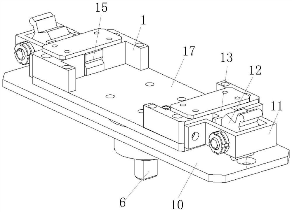
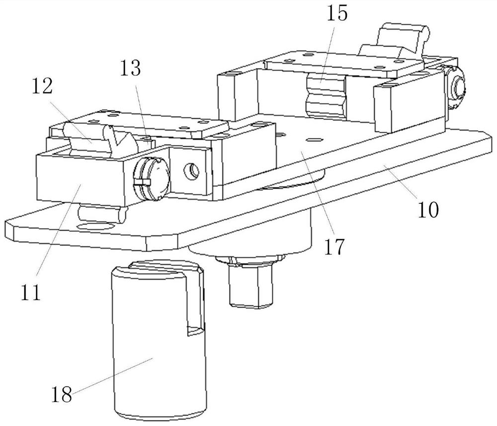
The invention discloses a self-locking elastic clamping device capable of freely combining rotation. The device comprises a rotating plate, a mounting plate and a flat square shaft, the flat square shaft is fixed to the bottom of the rotating plate, the mounting plate is located below the rotating plate, a mounting hole is formed in the mounting plate, and the flat square shaft is rotationally connected into the mounting hole through a bearing; the two ends of the rotating plate are provided with symmetrically-arranged turning-shaped components, the outer end faces of the turning-shaped components are connected with cam supports, cams are rotationally connected into the cam supports, sliding channels are formed in the turning-shaped components, square clamping sliding blocks are slidably connected into the sliding channels, one ends of the square clamping sliding blocks make contact with the cams, and the other ends of the square clamping sliding blocks make contact with the cams. The other end of the square clamping sliding block is provided with a V-shaped groove clamping sliding block which is telescopically connected with the square clamping sliding block, and a V-shaped groove is formed in the end face of the inner side of the V-shaped groove clamping sliding block, so that a workpiece can be accurately and rapidly clamped and positioned, assembly line work can be carried out, manpower resources are saved, the working efficiency is improved, safety and reliability are achieved, and equipment is convenient to disassemble and assemble during maintenance.

Description

technical field [0001] The invention relates to the technical field of clamps, in particular to a self-locking elastic clamping device which is freely combined and rotated. Background technique [0002] Fixture refers to the device used to fix the processing object in the process of mechanical manufacturing so that it occupies the correct position to accept construction or inspection. In a broad sense, any process in the process, the device used to install the workpiece quickly, conveniently and safely, can be called a fixture. In the prior art, common fixtures are often used for clamping and fixing workpieces, which requires manual operation of the locking handle, and cannot clamp multiple workpieces at the same time for assembly line operation, resulting in low efficiency and inability to clamp and position workpieces accurately and quickly. shortcoming. Therefore, it is necessary to propose a self-locking elastic clamping device that is freely combined and rotated to so...

Claims


Application Information

Patent Timeline
Patent Type & Authority Applications(China)
IPC IPC(8): B23Q3/06
CPCB23Q3/06
Inventor 黄凯
Owner 铜陵福茂再生资源利用有限公司
Learn More