
Binding iron wire cutting device based on constructional engineering

A technology of construction engineering and iron wire, applied in the field of iron wire guillotine device, can solve the problems of slow efficiency and low safety of iron wire, etc.

Pending Publication Date: 2022-05-13
张权
View PDF0 Cites 0 Cited by
  • Summary
  • Abstract
  • Description
  • Claims
  • Application Information

AI Technical Summary

Problems solved by technology

[0004] In order to overcome the disadvantages of low safety and slow efficiency of manual cutting of iron wire with guillotine, the purpose of the present invention is to provide a binding iron wire cutting device based on construction engineering with high safety and high efficiency

Method used


Image

  • Binding iron wire cutting device based on constructional engineering
  • Binding iron wire cutting device based on constructional engineering
  • Binding iron wire cutting device based on constructional engineering

Examples


Embodiment 1

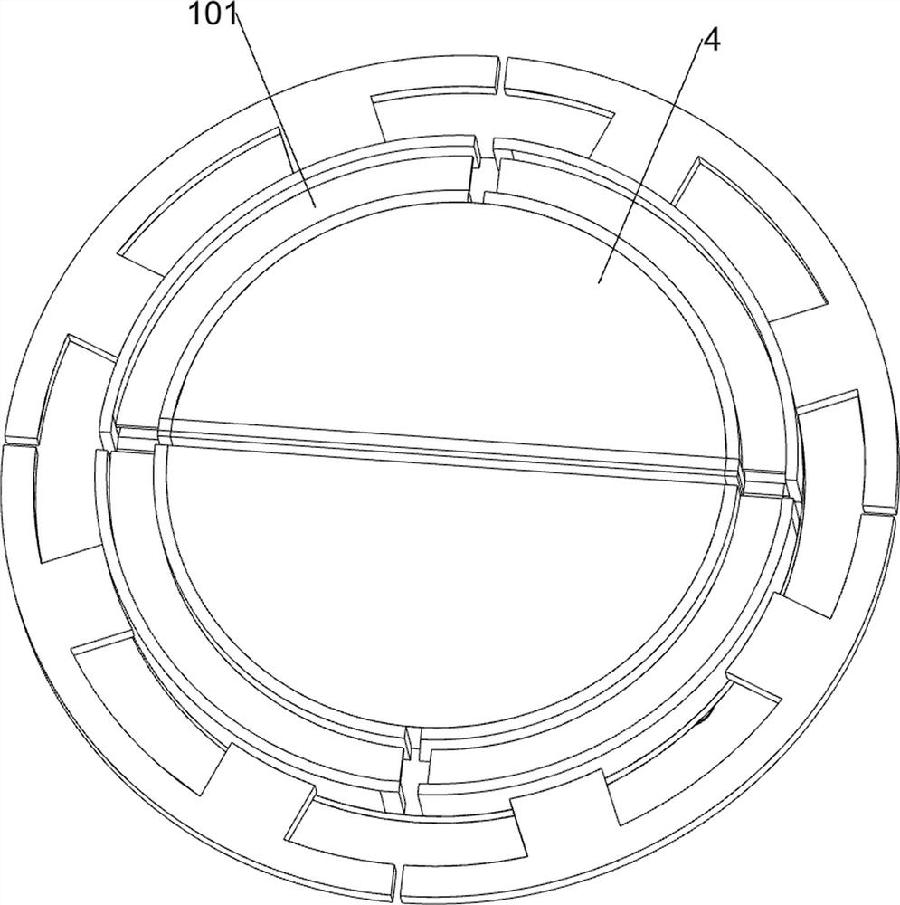
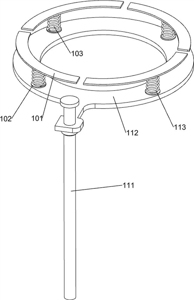
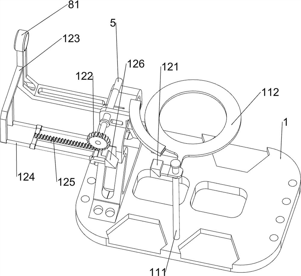
[0030] A binding wire cutting device based on construction engineering, such as Figure 1-9 As shown, it includes a base plate 1, a first support frame 2, a first slide rail 3, a first movable plate 4, a first rotating shaft 5, a fixed block 6, a blade 7, a pushing mechanism 8 and a rotating mechanism 9, and the left and right sides of the base plate 1 are The first support frame 2 is symmetrically arranged, and the top of the first support frame 2 is symmetrically provided with the first slide rail 3 front and rear, and the first movable plate 4 is slidably connected between the inner sides of the first slide rail 3, and the first slide rail on the left side The first rotating shaft 5 is rotationally connected between the left side of the rail 3, and the rear side of the first rotating shaft 5 is provided with two fixed blocks 6, and the rear side of the first rotating shaft 5 is provided with a blade 7, and the blade 7 is located between the fixed blocks 6. A push mechanism ...


PUM


Abstract

The invention relates to an iron wire cutting device, in particular to a binding iron wire cutting device based on constructional engineering. The invention aims to provide the binding iron wire cutting device based on constructional engineering, which is relatively high in safety and relatively high in efficiency. According to the technical scheme, the binding iron wire cutting device based on constructional engineering comprises a bottom plate, first supporting frames, first sliding rails, a first movable plate, a first rotating shaft, a fixing block and a blade, the first supporting frames are symmetrically arranged at the top of the bottom plate, and the first sliding rails are symmetrically arranged at the tops of the first supporting frames; a first movable plate is slidably connected between the opposite sides of the first sliding rails. According to the device, the rotating mechanism is arranged, a first rack drives a first one-way gear to rotate, then a second rotating shaft, a third movable plate and a first movable plate are driven to rotate, iron wires can be evenly cut, and the first movable plate does not need to be manually controlled to rotate.

Description

technical field [0001] The invention relates to an iron wire cutting device, in particular to a binding iron wire cutting device based on construction engineering. Background technique [0002] Iron wire is a commonly used building material in construction projects. Newly purchased iron wires are packed in rings. When a large number of iron wires of the same length are needed, the entire plate of iron wires needs to be cut. At present, people generally use a guillotine to cut iron wires. When cutting, One person needs to hold the iron wire, and one person operates the guillotine to cut the wire. Since the guillotine is cutting, the hand of the worker who grasps the iron wire is closer to the guillotine. If the guillotine slips, it is easy to accidentally injure the hand. The guillotine cuts the wire, and the efficiency is relatively slow. [0003] Therefore, it is necessary to develop a more secure and more efficient binding wire cutting device based on construction enginee...

Claims


Application Information

Patent Timeline
Patent Type & Authority Applications(China)
IPC IPC(8): B21F11/00
CPCB21F11/00
Inventor 张权
Owner 张权
Learn More