


Quick Research
Generate reliable direction feasibility study reports for your R&D in just a few steps.

Technical Q&A
Discover and master advanced knowledge NOW. Basics, ideas, possibilities, all at once.

Find Solutions
As an expert in R&D theories, this can generate solutions to your technical problems instantly.

Evaluate Feasibility
Analyze your overall solution with one click, know your potential R&D risks in advance.

Monitor Landscape
Get weekly tech updates, stay abreast of the latest tech innovations and key insights.
Positioning mechanism for die casting of cinerary casket storage rack
A positioning mechanism and storage rack technology, applied in positioning devices, storage devices, metal processing equipment, etc., can solve the problem that it is difficult to ensure that the position of the urn storage rack does not shift, and achieve the effect of reducing cumbersomeness
- Summary
- Abstract
- Description
- Claims
- Application Information
AI Technical Summary
Problems solved by technology
Method used
Image

Examples
Embodiment 1
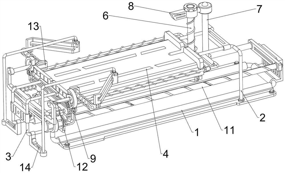
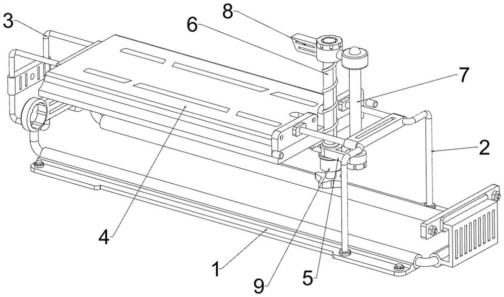
[0038] A positioning mechanism for die-casting of an urn storage rack, now for reference Figure 1-Figure 4 , including a bottom frame 1, a first mounting frame 2, a second mounting frame 3, a workbench 4, a mounting block 5, a screw rod 6, a guide rod 7, a lifting block 8, a rotating handle 9, a pushing mechanism 10 and a jacking mechanism 13 The right side of the top of the bottom frame 1 is installed with a first mounting frame 2 through bolts, and the bottom of the bottom frame 1 is equipped with an anti-slip pad, so that the bottom frame 1 is placed more stably. The left side of the bottom frame 1 is welded with a second mounting frame 3. A workbench 4 is welded between the first installation frame 2 and the second installation frame 3, the right side of the bottom of the workbench 4 is installed with a mounting block 5 through bolts, the left side of the mounting block 5 is rotatably connected with a rotating handle 9, and the top of the rotating handle 9 is riveted Ther...
Embodiment 2
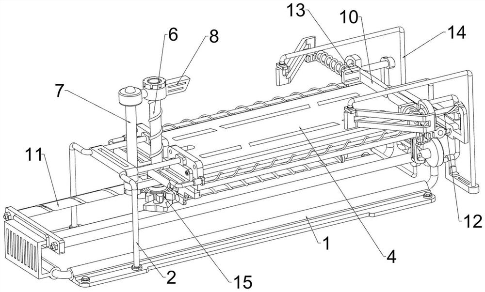
[0041] On the basis of embodiment 1, now refer to figure 2 , Figure 5 and Figure 6 As shown, the pushing mechanism 10 includes a support block 101, a connecting frame 102, a sliding block 103, a turret 104 and a return spring 105. The front and rear sides of the right side of the workbench 4 are welded with a support block 101, and the two support blocks 101 are connected to each other. The far side is connected with a connecting frame 102 by bolts, the left side of the two connecting frames 102 is slidably connected with a sliding block 103, and the two sliding blocks 103 are slidably connected with a turret 104, and the two turrets 104 are all slidably connected. Located on the top of the workbench 4, a return spring 105 is connected between the right side of the two sliding blocks 103 and the left side of the connecting frame 102 on the same side.
[0042] now refer to figure 1 , figure 2 , Figure 10 , Figure 11 and Figure 12 The jacking mechanism 13 includes ...
PUM
 Abstract
Description
Claims
Application Information
 - R&D Engineer
- R&D Manager
- IP Professional
- Industry Leading Data Capabilities
- Powerful AI technology
- Patent DNA Extraction
Browse by: Latest US Patents, China's latest patents, Technical Efficacy Thesaurus, Application Domain, Technology Topic, Popular Technical Reports.
© 2024 PatSnap. All rights reserved.Legal|Privacy policy|Modern Slavery Act Transparency Statement|Sitemap|About US| Contact US: help@patsnap.com