Multi-degree-of-freedom bionic exoskeleton body structure
An exoskeleton and degree-of-freedom technology, applied in the field of skeletal robots, can solve problems such as the limitation of bionic gait, and achieve flexible and diverse rehabilitation actions, easy to use, and simple and convenient operation
- Summary
- Abstract
- Description
- Claims
- Application Information
AI Technical Summary
Problems solved by technology
Method used
Image
Examples
Embodiment 1
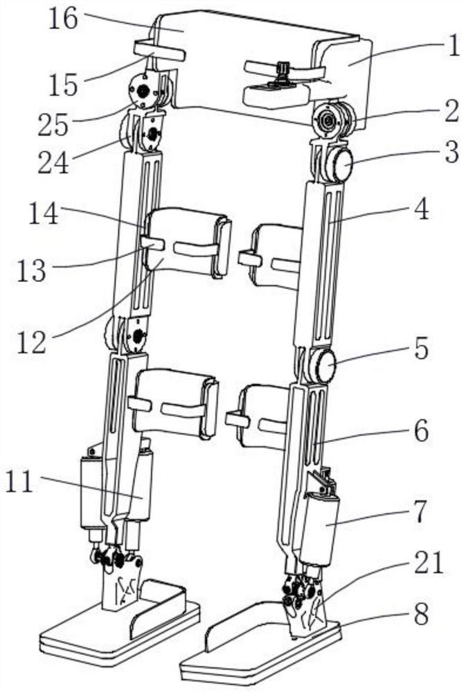
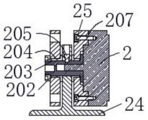
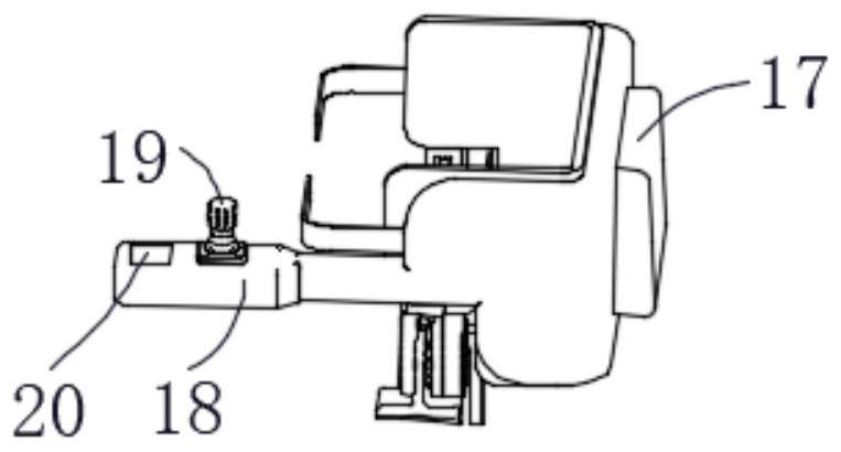
[0027] The present invention provides such Figure 1-5 The body structure of a multi-degree-of-freedom bionic exoskeleton shown includes a hip support mechanism 1, a hip joint flexion and extension motor 3, a thigh mechanism 4, a calf mechanism 6, a sole plate 8, a battery control box 17, a control handle 18 and protective gear Bandages, the lower end of the hip support mechanism 1 is provided with a hip joint abduction motor mounting part 25, the hip joint abduction motor mounting part 25 is connected with the rotating connector 24 through a rotating shaft 203, and the rotating shaft 203 is connected with the hip joint abduction motor mounting part Bushing bearing 204 is installed between 25, rotating shaft 203 is connected with bushing bearing 204 by locking screw 202, and rotating connector 24 is fixedly connected with rotating shaft 203 by fixed pin 205, when actually carrying out hip activity training, by controlling rotating shaft 203 rotates, and then drives the rotatin...
Embodiment 2
[0030] The difference between this embodiment 2 and embodiment 1 is that: the lower end of the thigh mechanism 4 is provided with a knee joint flexion and extension motor 5, and one end of the output shaft of the knee joint flexion and extension motor 5 is internally connected with the calf mechanism 6 through a coupling, and the knee joint flexion and extension motor 5 outputs The rotation direction of the shaft is parallel to the rotation direction of the output shaft of the hip joint flexion and extension motor 3, and the transmission mechanism of the knee joint flexion and extension motor 5 is similar to the hip joint flexion and extension motor 3, and then drives the knee joint flexion and extension motor 5 when the knee joint flexion and extension motor 5 is turned on The output shaft of the knee joint is rotated to drive the calf mechanism 6 connected to the output shaft of the knee joint flexion and extension motor 5 to realize the flexion and extension of the lower limb...
Embodiment 3
[0032]The difference between this embodiment 3 and embodiments 1 and 2 is that the sole plate 8 is fixedly installed on the lower end of the ankle joint part 21, the ankle joint part 21 is connected with the calf mechanism 6 through the cross sleeve 22, and one side of the ankle joint part 21 is provided with The ankle side linear motor 7, the other side of the ankle joint part 21 is provided with an ankle rear linear motor 11, the upper end of the ankle rear linear motor 11 is connected with a ten-byte 115, and the ankle rear linear motor 11 is fixedly installed on the calf mechanism through the first pin shaft 112 6. On the other side, the lower end of the linear motor 11 behind the ankle is provided with a spherical bearing 113, and the inside of the ankle joint part 21 is provided with a mounting hole, and the spherical bearing 113 is matched with the mounting hole. In order to realize the 2 degrees of freedom movement of the ankle joint, the rotation action can be realized...
PUM
 Abstract
Description
Claims
Application Information
 - R&D Engineer
- R&D Manager
- IP Professional
- Industry Leading Data Capabilities
- Powerful AI technology
- Patent DNA Extraction
Browse by: Latest US Patents, China's latest patents, Technical Efficacy Thesaurus, Application Domain, Technology Topic, Popular Technical Reports.
© 2024 PatSnap. All rights reserved.Legal|Privacy policy|Modern Slavery Act Transparency Statement|Sitemap|About US| Contact US: help@patsnap.com


