Sliding block type variable-diameter plunger and using method thereof

A variable and plunger technology, applied in the direction of earthwork drilling, wellbore/well components, production fluid, etc., to achieve the effect of solving technical bottlenecks

Pending Publication Date: 2022-05-10
CNOOC ENERGY TECH & SERVICES
View PDF7 Cites 0 Cited by
  • Summary
  • Abstract
  • Description
  • Claims
  • Application Information

AI Technical Summary

Problems solved by technology

In the existing technology, the drainage and gas production plunger can only pass through a single-diameter production string without a downhole safety valve installed

Method used


Image

  • Sliding block type variable-diameter plunger and using method thereof
  • Sliding block type variable-diameter plunger and using method thereof
  • Sliding block type variable-diameter plunger and using method thereof

Examples


Embodiment 1

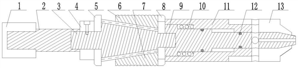
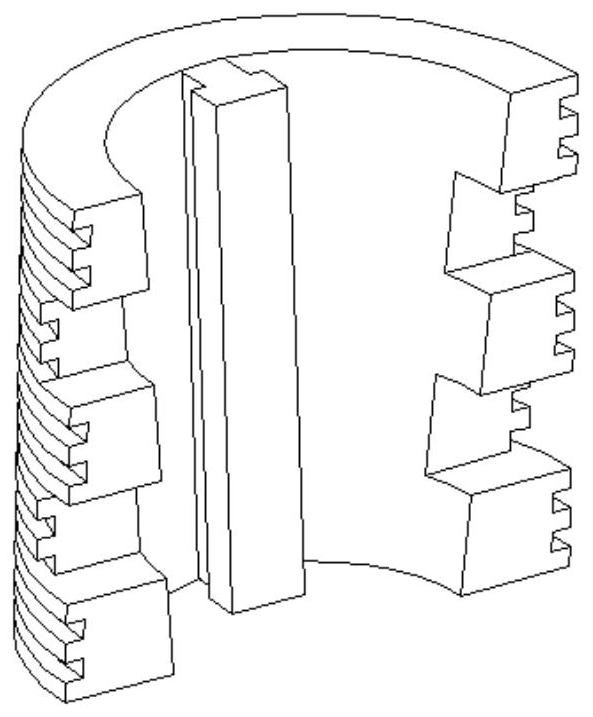
[0023] A slider-type variable-diameter plunger, including an upper connecting body 3, an upper anti-collision ring 5, an upper staggered tooth 6, a lower staggered tooth 7, a lower anti-collision ring 8, a lower connecting body 9, a piston 11 and a piston end cap 13. The upper part of the upper connecting body 3 adopts a columnar structure with a rectangular longitudinal section, the middle part of the upper connecting body 3 adopts a conical structure with an inverted isosceles trapezoidal longitudinal section, and the lower part of the upper connecting body 3 adopts a columnar structure with a rectangular longitudinal section , the upper anti-collision ring 5 and the lower anti-collision ring 8 are respectively sleeved on the head and tail ends of the middle part of the upper connecting body 3, T-shaped grooves are symmetrically opened on both sides of the outer wall of the middle part of the upper connecting body 3, and the upper staggered teeth 6 and The inner wall of the l...

Embodiment 2

[0025] On the basis of the first embodiment, a lock nut 4 is fixed on the outer wall of the upper connecting body 3 above the upper anti-collision ring 5 to prevent the upper anti-collision ring 5 from loosening and shifting.

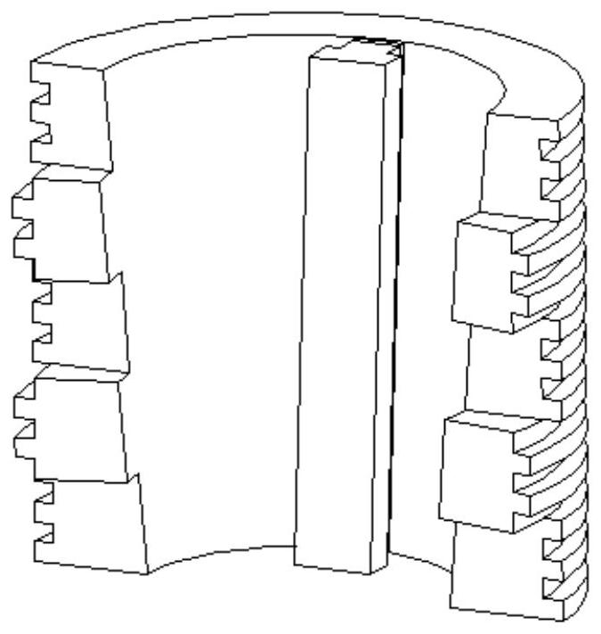
[0026] The inner wall of the upper staggered teeth 6 and the lower staggered teeth 7 adopts a tapered surface matched with the middle part of the upper connecting body 3, and a staggered tooth-shaped plug-in structure is formed at the edges of the upper staggered teeth 6 and the lower staggered teeth 7, so as to To achieve the purpose of connecting the upper staggered teeth 6 and the lower staggered teeth 7 , spiral grooves are uniformly arranged on the outer walls of the upper staggered teeth 6 and the lower staggered teeth 7 .

Embodiment 3

[0028] On the basis of the second embodiment, the outer wall of the head end of the upper connecting body 3 is threadedly connected to the inner wall of the tail end of the fishing head connecting rod 2 , and the outer wall of the head end of the fishing head connecting rod 2 is threadedly connected to the inner wall of the tail end of the fishing head 1 .

[0029] A sealing ring 12 is provided at the sealing place between the outer wall of the lower connecting body 9 and the inner wall of the piston 11 .


PUM


Abstract

According to the sliding block type variable-diameter plunger and the using method thereof, an upper anti-collision ring and a lower anti-collision ring are connected to the head end and the tail end of the middle of an upper connecting body in a sleeving mode correspondingly, upper staggered teeth and lower staggered teeth are slidably connected with the middle of the upper connecting body, and the outer wall of the tail end of the upper connecting body is in threaded connection with the inner wall of the head end of a lower connecting body; the piston is connected to the outer wall of the lower connecting body in a sleeved mode, the outer wall of the tail end of the lower connecting body is in threaded connection with the inner wall of the head end of the piston end cover, the piston end cover is of a hollow tubular structure with the head end open, air inlet holes are evenly formed in the side wall of the piston end cover, and a positioning shaft shoulder is formed on the outer wall of the upper portion of the lower connecting body. A limiting reducing section is formed in the middle of the inner wall of the piston, and a spring is arranged in a cavity formed by the lower surface of the positioning shaft shoulder, the inner wall of the piston, the upper surface of the limiting reducing section and the outer wall of the lower connecting body. The semi-staggered teeth climb along the conical surface sliding block to achieve plunger diameter changing, the plunger is attached to the inner wall of an oil pipe under the diameter changing working condition, and the output of a gas well is improved through a spiral groove sealing structure.

Description

technical field [0001] The invention relates to the technical field of a variable-diameter drainage and gas production plunger, in particular to a slider-type variable-diameter plunger and a use method thereof. Background technique [0002] At present, during the production of gas wells, with the decline of gas reservoir productivity and the emergence of groundwater production, fluid accumulation occurs in the wellbore, which seriously affects the production of gas wells and reduces the production efficiency of gas wells. Therefore, it is necessary to use plunger drainage gas recovery technology Drain the wellbore fluid, reduce the wellbore fluid level, and increase the bottom hole pressure difference, so as to achieve continuous and stable production. [0003] In the existing natural gas development, in order to ensure the safety of well control, the production and completion of high-pressure and high-risk gas wells on land, and the production and completion strings of all ...

Claims


Application Information

Patent Timeline
Patent Type & Authority Applications(China)
IPC IPC(8): E21B43/00
CPCE21B43/00
Inventor 田继宏邹先雄徐文江陈永锋张渊王晋莫高武李伟胡秉磊
Owner CNOOC ENERGY TECH & SERVICES
Why Eureka
Try Eureka