
Multi-working-condition buoyancy adjusting device and adjusting method

A technology of buoyancy adjustment and adjustment method, which is applied in the direction of transportation and packaging, special-purpose vessels, underwater operation equipment, etc., can solve the problems of large axial size of piston cylinder, small adjustable range, unfavorable device balance and stability, etc., to achieve Strong practicability, increased buoyancy adjustment range, beneficial to balance and stability

Active Publication Date: 2022-05-10
JIANGSU UNIV OF SCI & TECH
View PDF10 Cites 0 Cited by
  • Summary
  • Abstract
  • Description
  • Claims
  • Application Information

AI Technical Summary

Problems solved by technology

The patent number is CN102975835A (seawater piston-adjustable gliding submersible), and its overall structure is as follows: Figure 10 As shown, the submersible adopts a single-cylinder piston-cylinder structure, and the purpose of buoyancy adjustment is achieved through the water absorption and drainage of the single-side piston cylinder 6 in the figure, but the axial dimension of the piston cylinder in this structure is too large, and the adjustable range Too small, and the single-cylinder design structure is not conducive to the balance and stability of the overall device
[0003] The patent number is CN202120973457.6 (a center of mass buoyancy adjustable controllable buoyancy adjustment attitude controller) Although it is proposed that the center of mass of the device will change when the buoyancy is adjusted, it does not give a specific calculation method and formula for determining the center of mass
[0004] The patent number is CN202020404403.3 (a buoyancy adjustment mechanism and an underwater vehicle with the buoyancy adjustment mechanism). It can only realize the floating and submerging working conditions of the device, which cannot meet the requirements of various working conditions in the sea

Method used


Image

  • Multi-working-condition buoyancy adjusting device and adjusting method
  • Multi-working-condition buoyancy adjusting device and adjusting method
  • Multi-working-condition buoyancy adjusting device and adjusting method

Examples


Embodiment Construction

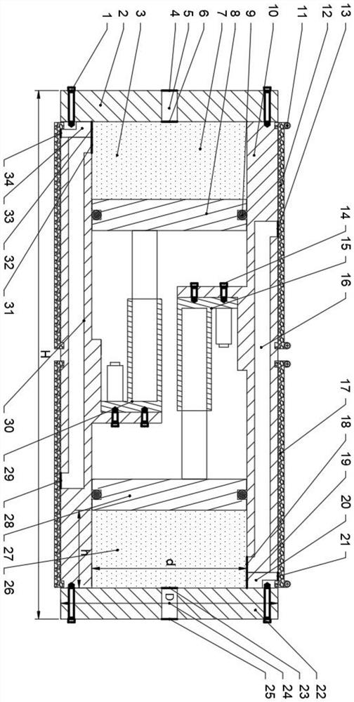
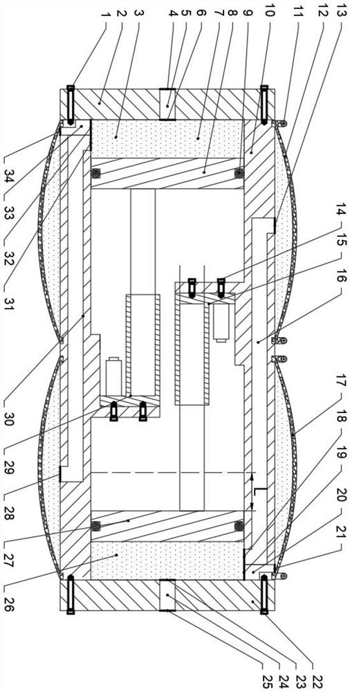
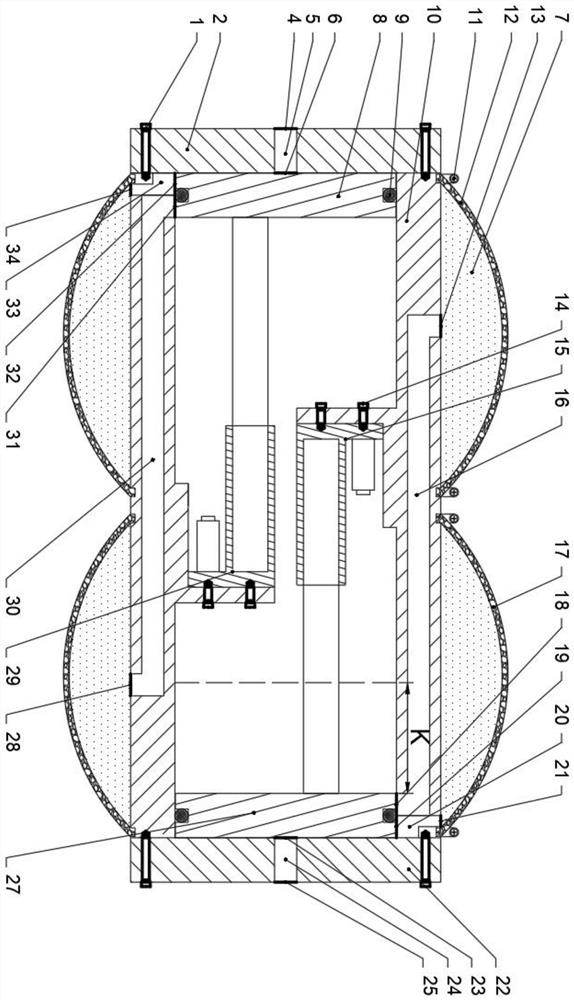
[0073] Such as Figure 1 to Figure 9 As shown, the multi-condition buoyancy adjustment device of the present invention includes a cabin body 10, a thrust assembly, a cavity assembly and a rubber bladder assembly; the cavity assembly includes a first cavity 3 and a second cavity 26; the rubber bladder assembly includes a first rubber The bladder 12 and the second rubber bladder 17; the thrust assembly includes a first thrust assembly and a second thrust assembly; wherein the first thrust assembly includes a first electric push rod 15 and a second piston 27; the second thrust assembly includes a second electric push rod 29 and the first piston 8.

[0074] The rubber bladder assembly is fixed with the cabin body 10 by the clamp 11, and the oil is stored in the first cavity 3 and the second cavity 26. Wherein the left end cover 2 and the right end cover 22 are fixed on the cabin body 10 by the first screw 1; the first electric push rod 15 and the second electric push rod 29 are f...


PUM


Abstract

The invention discloses a multi-working-condition buoyancy adjusting device and method. The buoyancy adjusting device comprises a cabin, a thrust assembly, a cavity assembly and a rubber bag assembly. The cavity assembly comprises a first cavity and a second cavity; the rubber capsule assembly comprises a first rubber capsule and a second rubber capsule; the thrust assembly comprises a first thrust assembly and a second thrust assembly; the thrust assembly adjusts the size and the gravity of the buoyancy adjusting device by controlling oil and water to enter and exit, and then the buoyancy and the posture of the buoyancy adjusting device are adjusted. When buoyancy adjustment is carried out, a calculation formula of the gravity center offset of the device, buoyancy calculation formulas corresponding to various working conditions and a state judgment method are given when the buoyancy adjustment device carries out pose transformation in water; the position change of the gravity center of the buoyancy adjusting device under various working conditions is calculated while buoyancy adjustment under multiple working conditions is carried out, various actual requirements are met, and the buoyancy adjusting device has practicability.

Description

technical field [0001] The invention relates to a buoyancy adjustment device for a marine vehicle, in particular to a multi-working-condition buoyancy adjustment device and an adjustment method. Background technique [0002] The buoyancy adjustment device of the marine vehicle is used to realize the submersion, floating, suspension, depth-fixed navigation and attitude adjustment of the vehicle, and is an indispensable part of the underwater vehicle to achieve free movement. The patent number is CN102975835A (seawater piston-adjustable gliding submersible), and its overall structure is as follows: Figure 10 As shown, the submersible adopts a single-cylinder piston-cylinder structure, and the purpose of buoyancy adjustment is achieved through the water absorption and drainage of the single-side piston cylinder 6 in the figure, but the axial dimension of the piston cylinder in this structure is too large, and the adjustable range Too small, and the single-cylinder design struc...

Claims


Application Information

Patent Timeline
Patent Type & Authority Applications(China)
IPC IPC(8): B63G8/22
CPCB63G8/22Y02E10/20
Inventor 张建刘畅程鹏展铭苏世杰殷宝吉李永胜唐文献
Owner JIANGSU UNIV OF SCI & TECH
Learn More