
Grafting printing method of selective laser melting equipment

A technology of melting equipment and laser selection, applied in the directions of additive manufacturing, additive processing, etc., can solve the problems of unadjusted substrate flatness, no detection method, and inability to locate z-axis, so as to ensure accuracy, efficient and reliable positioning, Practical effect

Active Publication Date: 2022-05-10
西安空天机电智能制造有限公司
View PDF9 Cites 0 Cited by
  • Summary
  • Abstract
  • Description
  • Claims
  • Application Information

AI Technical Summary

Problems solved by technology

However, this method relies more on human experience. There is no scientific detection method, and the z-axis direction cannot be positioned. It may cause the flatness of the substrate to be adjusted incorrectly and cause manufacturing failure.

Method used


Image

  • Grafting printing method of selective laser melting equipment
  • Grafting printing method of selective laser melting equipment
  • Grafting printing method of selective laser melting equipment

Examples


Embodiment Construction

[0047] The following will clearly and completely describe the technical solutions in the embodiments of the present invention with reference to the accompanying drawings in the embodiments of the present invention. Obviously, the described embodiments are some of the embodiments of the present invention, but not all of them. Based on the embodiments of the present invention, all other embodiments obtained by persons of ordinary skill in the art without making creative efforts belong to the protection scope of the present invention.

[0048] It should be understood that when used in this specification and the appended claims, the terms "comprising" and "comprises" indicate the presence of described features, integers, steps, operations, elements and / or components, but do not exclude one or Presence or addition of multiple other features, integers, steps, operations, elements, components and / or collections thereof.

[0049] It should also be understood that the terminology used ...


PUM

PropertyMeasurementUnit
depthaaaaaaaaaa
sizeaaaaaaaaaa

Abstract

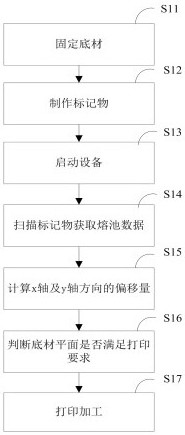
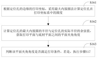
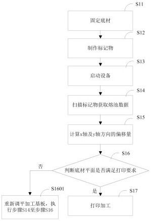
The invention discloses a grafting printing method of selective laser melting equipment. The grafting printing method comprises the steps that a substrate is fixed to a positioning clamp of a machining base plate; at least three positioning holes are drilled in the grafting face of the substrate, every three positioning holes form a triangular relation, and the positions of the positioning holes relative to the part are measured; the selective laser melting equipment is started, and a processing substrate is arranged in the selective laser melting equipment and is pre-buried and leveled; the coaxial molten pool monitoring device is started, the positioning hole is scanned, the edge of the positioning hole is recognized, and printing coordinates of the positioning hole are obtained according to scanning path information; the printing coordinates of the positioning holes are matched with the part coordinates of the positioning holes, and the offset in the x-axis direction and the offset in the y-axis direction between a printing coordinate system and a part coordinate system are obtained; the roundness of the positioning hole is obtained, the plane included angle between the printing plane and the substrate plane is obtained through calculation, whether the plane included angle meets the printing condition or not is judged, and if yes, printing machining is executed; and confirming printing coordinates of the grafting surface of the substrate, converting the printing coordinates into corresponding part coordinates, and carrying out printing processing.

Description

technical field [0001] The invention relates to the technical field of metal additive manufacturing, in particular to a graft printing method for laser selective melting equipment. Background technique [0002] Metal additive manufacturing has been widely used in aerospace, rail transit, medical health and other application fields, among which graft printing as a special manufacturing process is also showing a growing trend. [0003] Graft printing refers to the process of additively manufacturing parts from existing materials rather than from scratch. The substrate for graft printing is generally subtractively manufactured by traditional machining methods, while the part printed on it is additively manufactured. [0004] The biggest technical difficulty in metal additive manufacturing graft printing is substrate positioning. The working area of ​​additive manufacturing must completely coincide with the substrate, otherwise misalignment will occur. If there is a flow chan...

Claims


Application Information

Patent Timeline
Patent Type & Authority Applications(China)
IPC IPC(8): B22F10/28B33Y10/00B33Y50/02B22F10/366B22F10/85
CPCB22F10/28B22F10/366B22F10/85B33Y10/00B33Y50/02
Inventor 胡佳伟贺一轩田杏欢成星李庆
Owner 西安空天机电智能制造有限公司
Learn More