Pipeline mixer

A pipeline mixer and mixed flow technology, which is applied in the direction of fluid mixers, mixers, chemical instruments and methods, etc., can solve the problems of increasing equipment costs, etc., and achieve the effect of improving blending, intensifying mixing degree, and enhancing mixing effect

Active Publication Date: 2022-05-10
CHINA PETROLEUM & CHEM CORP +1
View PDF13 Cites 0 Cited by
  • Summary
  • Abstract
  • Description
  • Claims
  • Application Information

AI Technical Summary

Problems solved by technology

However, the mixer needs external compressed air, which increases the equipment cost

Method used


Image

  • Pipeline mixer
  • Pipeline mixer

Examples


Embodiment Construction

[0029] The pipeline mixer of the present invention will be further described below in conjunction with the accompanying drawings, and the following examples are used to illustrate the present invention, but do not constitute a limitation of the present invention.

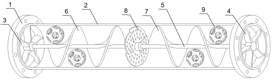
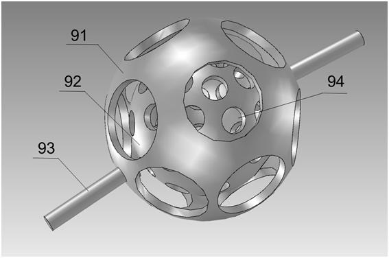
[0030] Such as Figure 1 to Figure 2 As shown, a pipeline mixer of the present invention mainly includes a flange 1, a pipe body 2, a right-handed blade 3, a left-handed blade 4, a central shaft 5, a left-handed helical impeller 6, a right-handed helical impeller 7, a porous shearing impeller 8, Double-layer hollow ball9. A pair of flanges 1 are provided at both ends of the pipe body 2, and the pipeline mixer is connected to the pipeline through the flanges 1; the flanges 1 at both ends are fixed and connected through the central shaft 5; the right-handed blade 3 is fixed inside the flange 1 at one end, and is connected with the right On the central axis 5 where the rotating blades 3 are coaxially connected, a left...


PUM


Abstract

The invention discloses a pipeline mixer. The mixer comprises a pipe body and a flange, a central shaft is arranged in the pipe body, at least one flow mixing assembly is arranged on the central shaft, and each flow mixing assembly sequentially comprises a right spiral impeller, a porous shearing impeller and a left spiral impeller. The multi-hole shearing impeller is composed of more than two blades, overlapped and staggered gaps are formed between the blades, and a plurality of small holes are formed in the blades. According to the pipeline mixer disclosed by the invention, the contact and mixing among various fluids are increased by increasing multiple times of reverse torsion of the fluids and the retention time of the fluids in the internal parts of the equipment, so that the purpose of improving the mixing effect is achieved.

Description

technical field [0001] The invention belongs to the technical field of fluid mixing devices, and in particular relates to a pipeline mixer. Background technique [0002] Pipeline mixer is a kind of mixer without any mechanical moving parts to achieve the purpose of uniform mixing through the action of a certain component or mixing element when the fluid flows through the pipeline. There are several types of pipeline mixers commonly used in industry, such as static baffle type, orifice type, and three-way mixer. The common static spiral plate mixer is developed on the perforated plate and special-shaped plate mixer. Each section of the mixer has a 180° twisted fixed spiral blade, which is divided into left-handed and right-handed. The helical blades in two adjacent sections rotate in opposite directions and are staggered by 90°. However, the mixing degree of this type of pipeline mixer for various fluids depends on factors such as the viscosity and flow rate of the fluid, a...

Claims


Application Information

Patent Timeline
Patent Type & Authority Applications(China)
IPC IPC(8): B01F25/431B01F33/82
CPCY02T10/30
Inventor 刘名瑞李遵照薛倩王晓霖赵巍李世瀚
Owner CHINA PETROLEUM & CHEM CORP
Why Eureka
Try Eureka