Split acoustic release device and release mechanism for subsurface buoy

A release device, split-body sound technology, applied in the direction of measuring devices, buoys, motor vehicles, etc., can solve the problems of high requirements for the use and maintenance of acoustic releasers, hazards to circuit boards and batteries, and increased cost of pressure-resistant shells, etc. Lightweight, improved reliability, and short communication distance

Pending Publication Date: 2022-05-06
GUANGDONG OCEAN UNIVERSITY
View PDF1 Cites 1 Cited by
  • Summary
  • Abstract
  • Description
  • Claims
  • Application Information

AI Technical Summary

Problems solved by technology

[0004] However, the motor-rotating shaft structure of the existing acoustic releaser is a dynamic seal, and the sealing reliability is low. Under the long-term deep-water high-pressure working condition, a small amount of seawater may pass through the dynamic seal (that is, the dynamic seal between the rotating shaft and the casing), Entering the inside of the case can cause fatal hazards to circuit boards and batteries
The dynamic seal between the rotating shaft and the pressure-resistant shell is a technical difficulty of the acoustic releaser, which has very high requirements for design, processing technology, engineering materials and maintenance. Before the submersible mark is laid, it should be checked whether the dynamic seal is

Method used


Image

  • Split acoustic release device and release mechanism for subsurface buoy
  • Split acoustic release device and release mechanism for subsurface buoy
  • Split acoustic release device and release mechanism for subsurface buoy

Examples


Embodiment 1

[0037] refer to figure 1 , generally shows the structure of the submersible buoy according to the first embodiment of the present invention and the split acoustic release device for the submersible buoy, the split acoustic release device includes a controller 113, the underwater unit 101 of the underwater acoustic communication machine and the release part 119, the signal cable 103 is connected to the controller 113, the underwater unit 101 and the release part 119, the controller 113 establishes a data connection with the deck unit through the underwater unit 101, and after completing mutual identity authentication, after receiving the release of the deck unit In the case of a command from the gravity anchor 120, the command is converted into a relay control signal and sent to the release unit 119, and the release unit 119 executes the command to release the anchor chain 110, and the submerged buoy floats up and recovers under the buoyancy of the main buoyant ball 114.

[003...

Embodiment 2

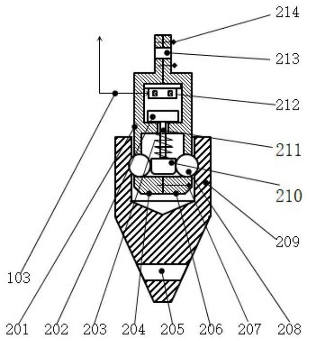
[0048] refer to Figure 5 and Figure 6 , shows the release part 119 according to the second embodiment of the present invention, the release part 119 includes hexagon socket bolts 501, 509, cable holes 502, left bracket 503, right bracket 504, male connector 505, female connector 506, Second suction cup electromagnet 507, anchor chain hole 508, wedge-shaped block 510, wedge-shaped end 511, corrosion-resistant springs 512, 515, ejector rod 513, connection hole 514, coupling rod 516, ferromagnetic boss 517, signal cable 103.

[0049] It should be understood that, in the second embodiment, the upper connecting frame is protruded through the ejector rod 513 to engage with the lower connecting frame, therefore, the upper connecting frame is referred to as “male connecting piece 505” here and thereafter. , in the same way, the lower connecting frame is called "female connecting piece 506"; in addition, in this embodiment, the shape of the block is wedge-shaped, so the block is ca...

Embodiment 3

[0055] refer to Figure 7 , The split acoustic release device according to the present invention can also be used in a "parallel" manner to form the release mechanism 702 (here and subsequently, the release mechanism is also referred to as the parallel mechanism 702) to improve the reliability of submerged mark recovery. The parallel mechanism 702 connects the mooring cable 116 at the connection hole 703; the plastic steel ring 704 connects the lower connecting frame 209 and the steel chain 705, the steel chain 705 passes through the steel ring 706, and the steel ring 706 connects the anchor chain 110.

[0056] Preferably, the open steel ring is put into the lower connecting frame 209 and then welded to form a closed steel ring, and then plastic-steel ring 704 is made by overmolding.

[0057] The controller 113 sends a release command to one of the two split acoustic release devices, the first suction cup electromagnet 212 attracts the ferromagnetic disk 202, the stopper 210 r...


PUM


Abstract

The invention provides a split acoustic release device and release mechanism used in a subsurface buoy, the split acoustic release device comprises an underwater acoustic communication set underwater unit, a controller and a release part, and the release part comprises an upper connecting frame and a lower connecting frame; the at least one connecting piece is arranged in the upper connecting frame; the electromagnet is arranged in the upper connecting frame; the ferromagnetic disc and the check block are arranged in the upper connecting frame, the connecting rod is connected between the ferromagnetic disc and the check block, and the check block abuts against at least one connecting piece; the upper connecting frame is provided with at least one through hole corresponding to the at least one connecting piece, the lower connecting frame is provided with at least one clamping groove, and under the condition that the electromagnet is not electrified, the at least one connecting piece at least partially extends out of the at least one through hole and is clamped in the at least one clamping groove; and under the condition that the electromagnet is electrified, the electromagnet drives the ferromagnetic disc and drives the stop block to move, so that the at least one connecting piece is separated from the at least one clamping groove. The split acoustic release device provided by the invention at least can provide a lower pressure-resistant requirement.

Description

technical field [0001] The invention relates to a split acoustic release device for submerged targets and a release mechanism comprising the split acoustic release device. Background technique [0002] The submersible buoy can realize long-term continuous measurement of marine environmental parameters at the location where the submerged buoy is placed, and is one of the few important devices that can conduct fixed-point continuous observation of marine environmental parameters. For example, the CN201220748198.8 patent document discloses the basic structure of the 3500-meter submersible buoy: "It is formed in series by the following components: main buoy support, 50-meter kevlar rope, the first floating ball group, the first group of 1000-meter kevlar rope, the second Float group, the second group of 1000-meter kevlar rope, the third group of float ball, the third group of 1000-meter kevlar rope, the fourth group of float ball, the releaser group, and the mooring system. The ...

Claims


Application Information

Patent Timeline
IPC IPC(8): B63B22/04B63B22/08G01C13/00
CPCB63B22/04B63B22/08G01C13/00
Inventor 王淑青雷桂斌彭银桥邱丽瑶施旭东
Owner GUANGDONG OCEAN UNIVERSITY
Why Eureka
Try Eureka