Main cone assembly leading-in device

A technology for introducing devices and components, which is applied to assembly machines, metal processing equipment, manufacturing tools, etc. It can solve the problems of many manual steps, low production efficiency, and complicated assembly process, so as to improve work efficiency and smooth press assembly , the effect of accurate positioning

Pending Publication Date: 2022-05-06
GUANGDONG FUWA HEAVY IND
View PDF0 Cites 0 Cited by
  • Summary
  • Abstract
  • Description
  • Claims
  • Application Information

AI Technical Summary

Problems solved by technology

[0002] The main reducer of the automobile includes the reduction housing and the active bevel gear assembly installed in the reduction housing. Because the active bevel gear is generally integrated with the shaft, it is also called the main bevel, so the active bevel gear assembly is also called the main bevel assembly. , the main cone assembly includes the main cone assembly, the main cone assembly includes the main cone, the cone bearing, the cylindrical bearing and the circlip used to limit the axial movement of the cylindrical bearing. In the process of assembling the main cone assembly, the operator first puts the main cone shaft The bottom of the hydraulic press is placed on the workbench of the hydraulic press, and then the hydraulic press is started. The main shaft of the hydraulic press presses the cylindrical gear onto the main cone shaft, and then the operator uses a caliper to snap the circlip into the outer circumference of the shaft end of the main cone shaft. Then put the bottom down on the workbench of the hydraulic press, and then turn on the hydraulic press. The main shaft of the hydraulic press will press-fit the bevel gear onto the main cone shaft to complete the assembly of the main cone assembly. It can be seen that the above The manual operation of the assembly method has many steps, which makes the assembly process complicated and time-consuming, resulting in low production efficiency

Method used


Image

  • Main cone assembly leading-in device
  • Main cone assembly leading-in device
  • Main cone assembly leading-in device

Examples


Embodiment Construction

[0024] Below, in conjunction with accompanying drawing and specific embodiment, the present invention will be further described:

[0025] It should be noted that when an element is considered to be "connected" to another element, it may be directly connected to and integrally integrated with the other element, or there may be an intervening element at the same time. The terms "mounted", "one end", "the other end" and similar expressions are used herein for the purpose of description only.

[0026] Unless otherwise defined, all technical and scientific terms used herein have the same meaning as commonly understood by one of ordinary skill in the art of this technology. The terminology used in the description herein is only for the purpose of describing specific embodiments, and is not intended to limit the present invention. As used herein, the term "and / or" includes any and all combinations of one or more of the associated listed items.

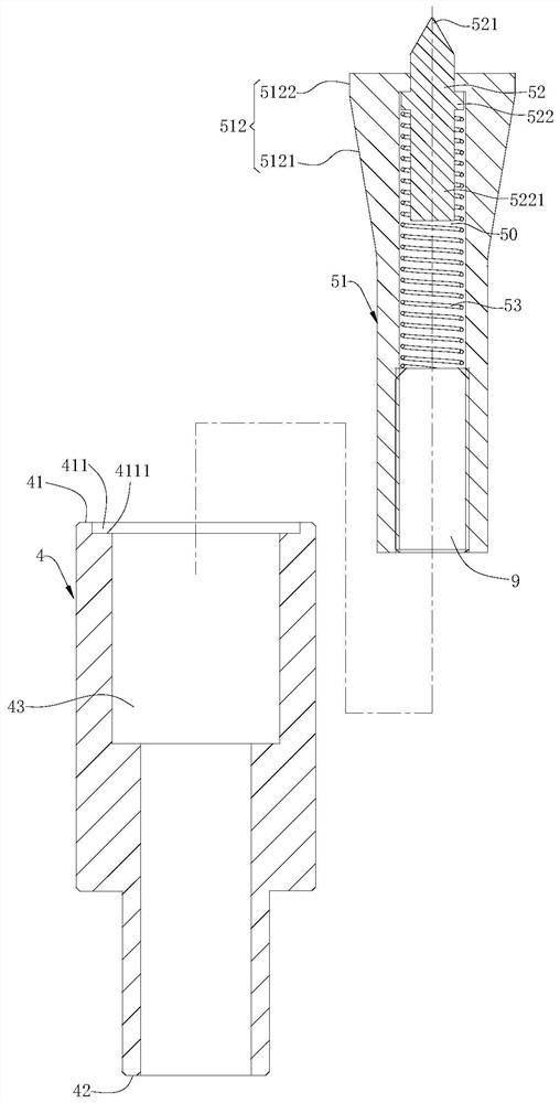
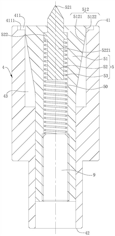
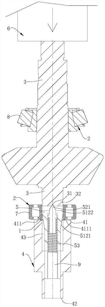
[0027] Such as Figure 1 to Figure ...


PUM


Abstract

The invention provides a leading-in device for a main cone assembly, which is used for assembling a clamp spring and a bearing on a main cone shaft of the main cone assembly, and comprises a base which is provided with a first surface and a second surface which are oppositely arranged, the first surface is used for supporting the bearing, the first surface is provided with a limiting mechanism for supporting the clamp spring, and the limiting mechanism is lower than the first surface; the base is provided with an accommodating cavity which is concavely formed from the first surface to the second surface; and the guide mechanism comprises a guide shaft telescopically installed in the containing cavity and a positioning piece installed in the guide shaft, the guide shaft is used for being sequentially sleeved with a clamping spring and a bearing, and the positioning end of the positioning piece stretches out of the guide shaft. By arranging the limiting mechanism, the clamping spring does not make contact with the cylindrical bearing, so that the resistance of the clamping spring guided into the main cone shaft is reduced, press fitting is smooth, the purpose of one-step press fitting of the conical bearing, the cylindrical bearing and the clamping spring in place can be achieved, then the main cone assembly can be rapidly assembled, and the working efficiency is improved.

Description

technical field [0001] The invention relates to the technical field of assembly of auto parts, in particular to a main cone component introducing device. Background technique [0002] The main reducer of the automobile includes the reduction housing and the active bevel gear assembly installed in the reduction housing. Because the active bevel gear is generally made integral with the shaft, it is also called the main cone, so the active bevel gear assembly is also called the main bevel assembly. , the main cone assembly includes the main cone assembly, the main cone assembly includes the main cone, the cone bearing, the cylindrical bearing and the circlip used to limit the axial movement of the cylindrical bearing. In the process of assembling the main cone assembly, the operator first puts the main cone shaft The bottom of the hydraulic press is placed on the workbench of the hydraulic press, and then the hydraulic press is started. The main shaft of the hydraulic press p...

Claims


Application Information

Patent Timeline
IPC IPC(8): B23P21/00
CPCB23P21/00
Inventor 吴志强彭毅中付正勇于鸣
Owner GUANGDONG FUWA HEAVY IND
Why Eureka
Try Eureka