Micromechanical z-axis inertial sensor and method for producing such sensor

A technology of micro-mechanics and axis inertia, which is applied in the direction of acceleration measurement, instrumentation, and micro-structure technology using inertial force, and can solve problems such as inability to accurately limit stop behavior and cost

Pending Publication Date: 2022-05-03
ROBERT BOSCH GMBH
View PDF1 Cites 0 Cited by
  • Summary
  • Abstract
  • Description
  • Claims
  • Application Information

AI Technical Summary

Problems solved by technology

A further disadvantage of stop knobs produced in this way is that only a downward stop is possible with them
If an upward stop is also to be implemented, additional technical effort is required
The stop behavior of the Z-axis acceleration sensor with the mentioned stop bumps is defined by layer deposition or layer etching, wherein, depending on the changing ratio, the relationship between the deposited layers may also change, so that it may not be possible Precisely define stop behavior

Method used


Image

  • Micromechanical z-axis inertial sensor and method for producing such sensor
  • Micromechanical z-axis inertial sensor and method for producing such sensor
  • Micromechanical z-axis inertial sensor and method for producing such sensor

Examples


Embodiment Construction

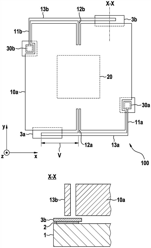
[0032] In the following, in order to describe the geometric relationship, it is considered that the substrate plane of the proposed micromechanical z-axis inertial sensor extends in the xy plane and that the vibrating mass element of the proposed micromechanical z-axis inertial sensor can be displaced in the z direction .

[0033] figure 1 A top view of a first embodiment of the proposed micromechanical z-axis inertial sensor 100 is shown.

[0034] An attachment element 30a can be seen, by means of which the first seismic mass element 10a is attached to the substrate 1 . In the event of an acceleration force acting on the first seismic mass element 10a, the first seismic mass element moves planarly downward or upward in the z-direction. Starting from the attachment element 30a, a first torsion spring element 11a can be seen, which can be twisted about the y-axis when the first seismic mass element 10a is offset parallel to the xy plane.

[0035] For the micromechanical z-ax...


PUM


Abstract

The invention relates to a micromechanical z-axis inertial sensor (100), comprising: at least one first vibration mass element (10a); and-a torsion spring element (11a... 11n, 12a... 12n) connected to the first vibration mass element (10a); wherein-first torsion spring elements (11a... 11n) are each connected to the substrate (1), and second torsion spring elements (12a... 12n) are each connected to the first vibratory mass elements (10a); wherein-the first and the second torsion spring elements (11a... 11n, 12a... 12n) are each connected to one another by means of a lever element (13a... 13n), said lever element (13a... 13n) being designed to stop on a stop element (3a... 3n). The invention also relates to a method for producing a micromechanical z-axis inertial sensor (100).

Description

technical field [0001] The invention relates to a micromechanical z-axis inertial sensor. The invention also relates to a method for producing a micromechanical z-axis inertial sensor. Background technique [0002] A stop concept for a micromechanical z-acceleration sensor is known from DE 10 2005 059 905 A1, in which a stop knob is provided on the underside of the movable structure, which stops against the stop surface and Movement in the z direction is thus defined. A disadvantage of producing such a stop knob is that additional technological steps are required. [0003] A further disadvantage of the mentioned stop concept is that the stop distance is set by the manufacturing process, which means that only stop bumps of a defined height are possible. A further disadvantage of stop knobs produced in this way is that only downward stops are possible with them. If an upward stop is also to be implemented, this would require additional outlay in terms of further engineerin...

Claims


Application Information

Patent Timeline
Patent Type & Authority Applications(China)
IPC IPC(8): G01P15/08G01P15/18
CPCG01P15/08G01P15/18G01P15/0802G01P2015/0831G01P2015/0871B81B3/0051B81B3/0013B81B2201/0235G01P15/125
Inventor J·赖因穆特
Owner ROBERT BOSCH GMBH
Why Eureka
Try Eureka