Rotating plate type magnetic flowmeter with anti-blocking structure

A flowmeter and rotary plate technology, applied in the field of flowmeters, can solve the problems of affecting the measurement accuracy, disturbing the magnetic field of the magnetic flowmeter, blocking the magnetic flowmeter, etc., to achieve the effect of prolonging the service life, preventing internal clogging and strong moisture resistance

Pending Publication Date: 2022-05-03
SHANGHAI ANJUN ELECTRONICS TECH
View PDF0 Cites 0 Cited by
  • Summary
  • Abstract
  • Description
  • Claims
  • Application Information

AI Technical Summary

Problems solved by technology

[0004] The purpose of the present invention is to provide a rotary plate magnetic flowmeter with an anti-blocking structure, to solve the above-mentioned background technology, the current pressure flowmeter mostly uses the differential pressure flowmeter, which uses the principle of differential pressure generated by the internal structure For flow measurement, such as orifice flowmeter, V-cone flowmeter, Annubar flowmeter, porous balance flowmeter, etc. Another speed flowmeter that measures flow velocity converts the flow velocity of the medium into mechanical rotation , by rotating and sending out pulse signals to indirectly measure flow, such as turbine flowmeters, etc. However, there is no research on combining pressure and magnetic force to form a new flowmeter, and the medium often contains metal impurities, which disturb the magnetic flowmeter. A large amount of impurities are adsorbed on the magnet, which not only affects the measurement accuracy, but also causes blockage inside the magnetic flowmeter over time.

Method used


Image

  • Rotating plate type magnetic flowmeter with anti-blocking structure
  • Rotating plate type magnetic flowmeter with anti-blocking structure
  • Rotating plate type magnetic flowmeter with anti-blocking structure

Examples


preparation example Construction

[0046] The preparation method of the rubber material is as follows: mix polystyrene butadiene rubber and nanomaterials evenly, add vulcanizing agent and accelerator, vulcanize and form, the vulcanization temperature is 145°C, and the vulcanization time is 500s.

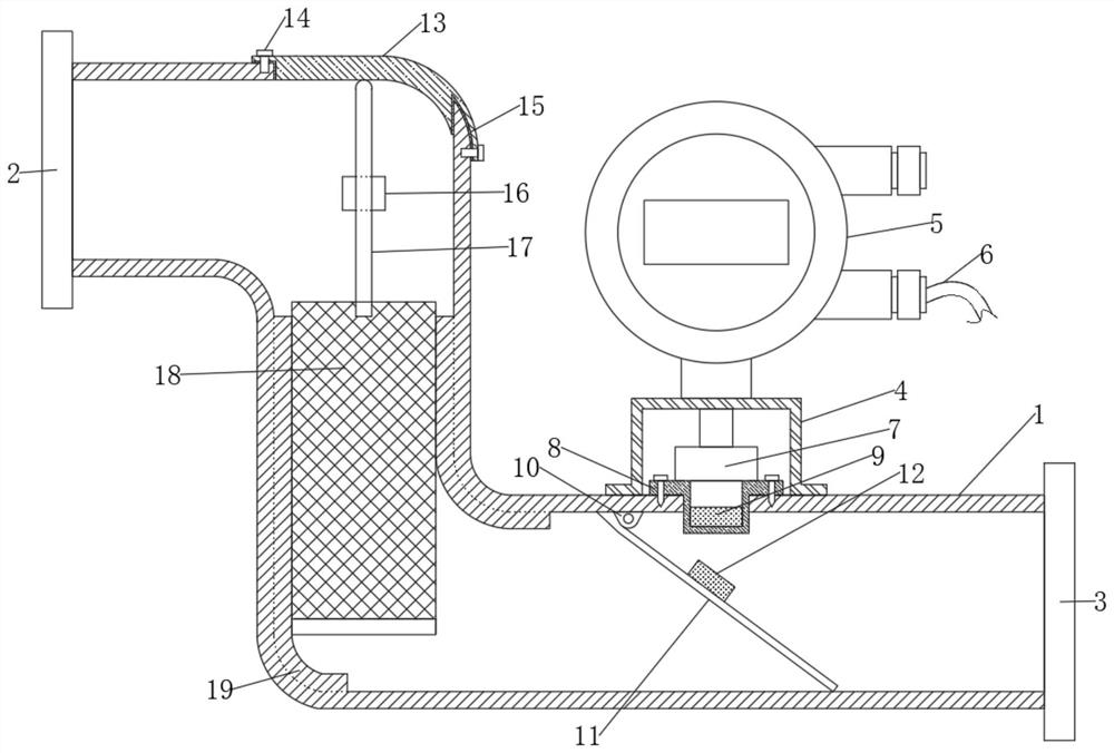
[0047] Further, the clips 16 are located on both sides of the front and back of the watch body 1, the thickness of the thickened pipe 19 is greater than the width of the clip 16, the filter bucket 18 is in sliding connection with the thickened pipe 19, and the pull rod 17 is in a sliding connection with the clip 16. The clamp 16 is a two-thirds ring structure, the pull rod 17 is an "n"-shaped structure, the inner diameter of the thickened pipe 19 is the same as the diameter of the filter barrel 18, and the watch body 1 is a "Z"-shaped structure, through the setting of the filter barrel 18 , separate the impurities entering the medium at the inlet flange 2, prevent metal impurities from being adsorbed on the second magn...

Embodiment 1

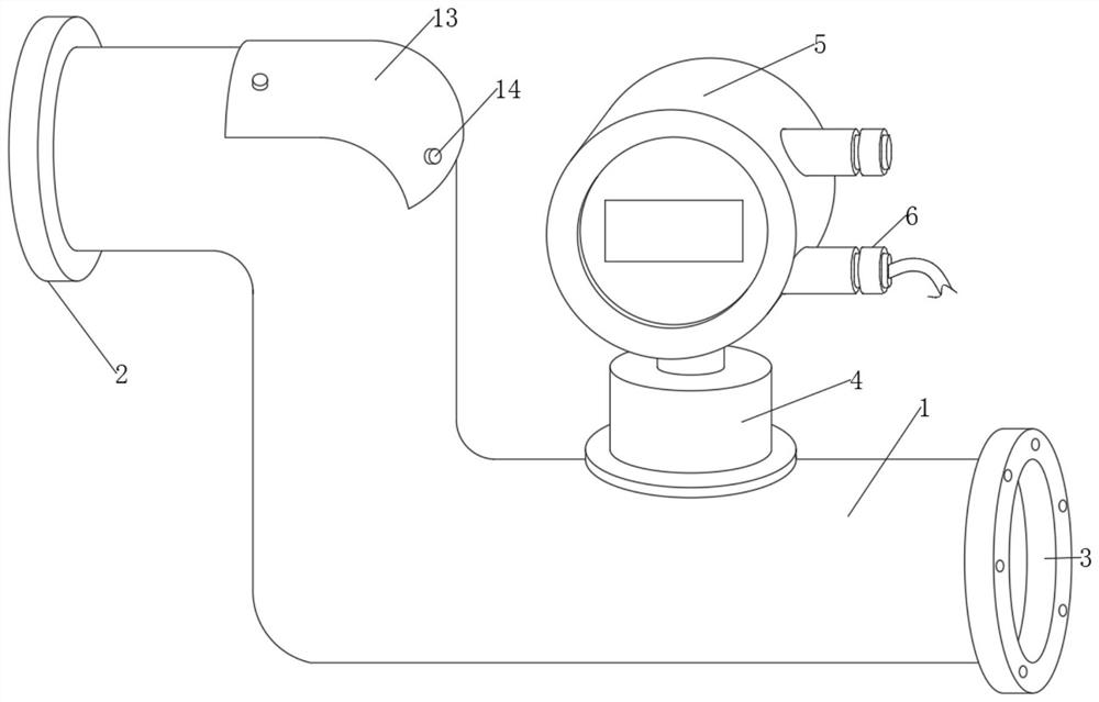
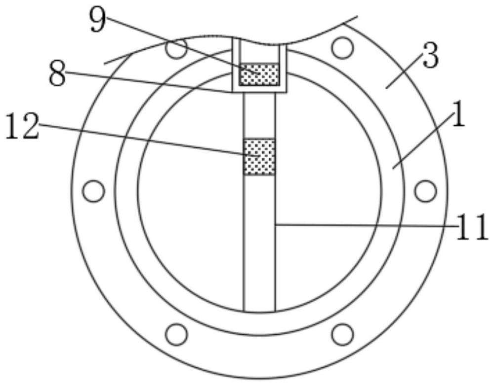
[0050] This embodiment provides a technical solution: a rotating plate magnetic flowmeter with an anti-blocking structure, including a meter body 1, an inlet flange 2, an outlet flange 3, a support 4, an accumulator 5, a terminal 6, Pressure sensor 7, magnetic base 8, first magnet 9, hinge bracket 10, rotating plate 11, second magnet 12, sealing cover 13, screw 14, sealing gasket 15, clip 16, pull rod 17, filter bucket 18 and thickening Pipeline 19, inlet flange 2 is fixedly installed on the left side of meter body 1, outlet flange 3 is fixedly installed on the right side of meter body 1, support 4 is fixedly installed on the outside of meter body 1, and the top of support 4 is provided with The totalizer 5 is provided with a terminal 6 on the outside of the totalizer 5, a pressure sensor 7 is provided inside the support 4, a magnetic base 8 is fixedly installed on the inside of the meter body 1, and the bottom of the magnetic base 8 is provided with a first Magnet 9, watch bo...

Embodiment 2

[0060] The difference between this embodiment and Embodiment 1 is that the rubber material is different.

[0061] The rubber material includes the following raw materials in parts by weight: 75 parts of solution-polymerized styrene-butadiene rubber (LANXESS Chemical 5025-2HM), 15 parts of graphene oxide (Xianfeng Nano), 5 parts of sulfur (Luchu rubber), 2.5 parts of accelerator Agent CZ (CAS: 95-33-0). The styrene block content of the solution polystyrene butadiene rubber is 0.3wt%. The density of the graphene oxide is 0.9 g / mL at 25°C.


PUM


Abstract

The rotating plate type magnetic flow meter with the anti-blocking structure comprises a meter body, an inlet flange is fixedly installed on the left side of the meter body, and an outlet flange is fixedly installed on the right side of the meter body. According to the rotating plate type magnetic flowmeter with the anti-blocking structure, the N poles or S poles of the same poles of the first magnet and the second magnet are oppositely arranged, so that the higher the flow rate of a medium is, the closer the rotating plate to the magnetic base is, the repulsive force between the second magnet and the first magnet is relatively increased, and the lower the flow rate of the medium is, the smaller the repulsive force between the second magnet and the first magnet is; corresponding flow is calculated through the integrating instrument according to changes of magnetic force, a rotating plate arranged in the meter body rotates through changes of flow speed, a second magnet is installed on the rotating plate, a first magnet with the same magnetic pole is installed on the corresponding meter body, the distance between the magnets is changed through rotation of the rotating plate, and therefore changes of repulsive force are changed. The change of the magnetic force and the change of the flow are linear, and the flow is measured by measuring the change of the magnetic force.

Description

technical field [0001] The invention relates to the technical field of flowmeters, in particular to a rotary plate magnetic flowmeter with an anti-blocking structure. Background technique [0002] Flowmeter, defined by the National Committee for Scientific and Technical Terms as: an instrument that indicates the measured flow rate and (or) the total amount of fluid in a selected time interval. Flowmeters are divided into differential pressure flowmeters, rotameters, throttling flowmeters, slit flowmeters, volume flowmeters, electromagnetic flowmeters, and ultrasonic flowmeters. Specifically, it is a flowmeter with an anti-blocking structure rotary plate magnetic flowmeter. [0003] The current pressure flowmeter mostly uses the differential pressure flowmeter, which uses the principle of differential pressure generated by the internal structure to measure the flow, such as orifice flowmeter, V-cone flowmeter, Annubar flowmeter, porous balance flowmeter, etc. Another type o...

Claims


Application Information

Patent Timeline
IPC IPC(8): G01F1/20G01F15/00G01F15/07G01F15/12G01F15/18C08L9/06C08K13/02C08K3/04C08K3/34
CPCG01F1/206G01F15/006G01F15/07G01F15/125G01F15/185C08K13/02C08K3/042C08K3/041C08K3/346C08K2201/011C08L9/06
Inventor 黄俊罗利
Owner SHANGHAI ANJUN ELECTRONICS TECH
Why Eureka
Try Eureka