Protective device for power distribution equipment of power system

A technology for power distribution equipment and protective devices, which is applied in the directions of substation/distribution device housing, substation/switchgear cooling/ventilation, substation/switch layout details, etc. Good and other problems to achieve the effect of reducing consumption and avoiding maintenance

Pending Publication Date: 2022-04-29
浙江易泽信息科技有限公司
View PDF0 Cites 0 Cited by
  • Summary
  • Abstract
  • Description
  • Claims
  • Application Information

AI Technical Summary

Problems solved by technology

[0006] The present invention provides a protection device for power distribution equipment in a power system, one of the purposes of which is to have the effect of improving the heat dissipation performance of the protection device for power distribution equipment, and to solve the problem of poor heat dissipation of the existing protection device for power distribution equipment. The internal temperature is too high and easy to damage, which requires frequent maintenance by the staff; another purpose is to solve the problem that the existing protective device for power distribution equipment only uses the box to protect its internal structure, and its protective effect is poor , the problem that the equipment is vulnerable to damage, in order to achieve the effect of avoiding damage to the equipment caused by the external environment

Method used


Image

  • Protective device for power distribution equipment of power system
  • Protective device for power distribution equipment of power system
  • Protective device for power distribution equipment of power system

Examples


Embodiment Construction

[0034] Below in conjunction with embodiment the present invention is described in further detail:

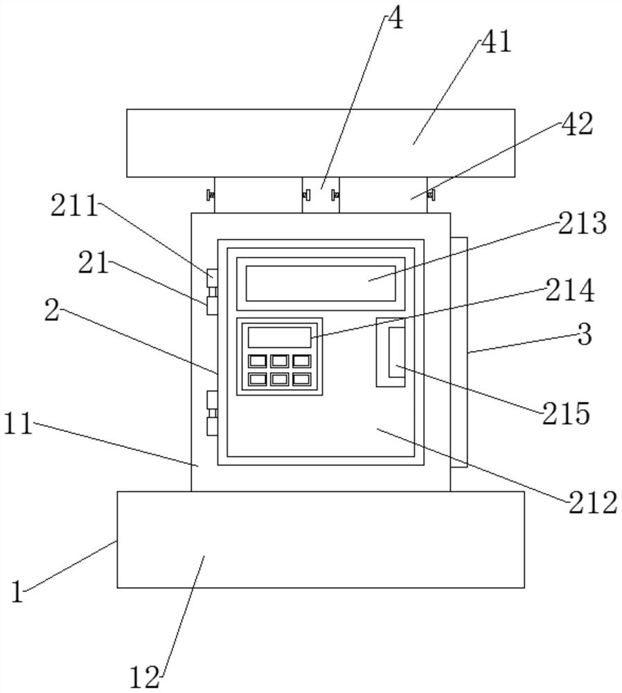
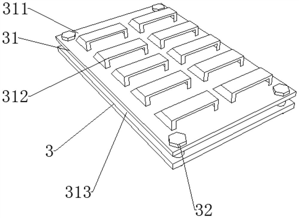
[0035] Such as Figure 1-6 As shown, it includes the main body mechanism 1, the front end of the main body mechanism 1 is provided with a heat dissipation mechanism 2, the right end of the main body mechanism 1 is provided with a dustproof mechanism 3, the upper part of the main body mechanism 1 is provided with a protection mechanism 4, and the front end of the heat dissipation mechanism 2 is provided with a closed device 21, and a driving device 22 is provided at the rear end of the closing device 21, a ventilation device 31 is provided inside the dustproof mechanism 3, and a fixing device 32 is provided outside the ventilation device 31, and a shield is provided above the protection mechanism 4. device 41 , and a docking device 42 is provided at the lower end of the shielding device 41 .

[0036] Preferably, the closing device 21 includes a hinge 211, the right end of the hi...


PUM


Abstract

The invention discloses a protection device for power distribution equipment of a power system, and relates to the technical field of power equipment, the protection device comprises a main body mechanism, a heat dissipation mechanism is arranged at the front end of the main body mechanism, a dustproof mechanism is arranged at the right end of the main body mechanism, and a protection mechanism is arranged above the main body mechanism. According to the invention, the mounting box is mounted on the back surface of the cabinet door through the fixing buckle, then the fan blades are protected through the protective shell, and then the fan blades are driven to rotate through the bearing, so that the equipment in the protective device is cooled, and the situation that the equipment breaks down due to too high temperature is prevented, thereby avoiding the situation that a worker frequently maintains the equipment, and improving the working efficiency. And the front baffle, the side baffles and the top plate are matched together to protect the box body, the bearing strength and the assembly firmness of the box body are improved through the ribs, sunscreen and waterproof protection is carried out on the equipment, and then the service life of the equipment is prolonged.

Description

technical field [0001] The invention relates to a protection device for power distribution equipment in a power system, relates to the technical field of power equipment, and in particular to a protection device for power distribution equipment in a power system. Background technique [0002] The power system is a power production and consumption system composed of power generation, power transformation, power transmission, power distribution and power consumption. Its function is to convert the natural primary energy into electric energy through the power generation device, and then supply the electric energy to each load center through the transmission, transformation system and distribution system. Since most of the power points and load centers are located in different regions and cannot be stored in large quantities, electricity production must always maintain a balance with consumption. Therefore, the centralized development and decentralized use of electric energy, a...

Claims


Application Information

Patent Timeline
IPC IPC(8): H02B1/56H02B1/28H02B1/38H02B1/30H02B1/32
CPCH02B1/565H02B1/28H02B1/38H02B1/30H02B1/32
Inventor 胡波严婵李红梅
Owner 浙江易泽信息科技有限公司
Why Eureka
Try Eureka