Driving circuit, driving chip and display device

A driving circuit and logic circuit technology, applied in static indicators, instruments, etc., can solve problems such as lack of brightness, and achieve the effects of flexible brightness compensation, accurate phase deviation or delay, and increased accuracy

Active Publication Date: 2022-04-29
CHENGDU LIPPXIN MICROELECTRONIC CO LTD
View PDF12 Cites 0 Cited by
  • Summary
  • Abstract
  • Description
  • Claims
  • Application Information

AI Technical Summary

Problems solved by technology

[0005] The purpose of this application is to overcome the deficiencies of the prior art, and to provide a driving circuit that can solve the problem of lack of brightness caused by the loss of display time in actual display, and can eliminate the problem caused by the passage of each clock in brightness compensation. The unknown phase deviation between the clock phases caused by combinational logic circuits and other reasons can be more accurately compensated

Method used


Image

  • Driving circuit, driving chip and display device
  • Driving circuit, driving chip and display device
  • Driving circuit, driving chip and display device

Examples


Embodiment Construction

[0046] The technical solution of the present application will be further described in detail below in conjunction with specific embodiments, but the protection scope of the present application is not limited to the following description.

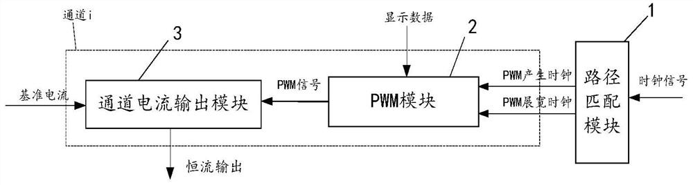
[0047] In one aspect, the present application provides a driving circuit, referring to figure 1 The schematic diagram of the driving circuit is shown, which includes:

[0048] The path matching module 1 is used to eliminate the unknown phase difference between the PWM stretched clock signal and the PWM generated clock signal;

[0049] The PWM module 2 generates a PWM signal based on the display data, the PWM generated clock signal and the PWM extended clock signal;

[0050] The channel current output module 3 outputs a constant current during the effective period of the PWM signal.

[0051] Optionally, the difference between the PWM stretched clock signal and the PWM generated clock signal is K complete clock periods, where 0≤K<1.

[005...


PUM


Abstract

The invention relates to a driving circuit, and the circuit comprises a path matching module which is used for eliminating an unknown phase difference between a PWM broadened clock signal and a PWM generated clock signal; the PWM module is used for generating a PWM signal based on display data, the PWM generation clock signal and the PWM broadening clock signal; and the channel current output module is used for outputting constant current during the effective period of the PWM signal. On one hand, the circuit can compensate the lighting time of the LED; and on the other hand, through a path matching mode, relatively accurate PWM phase compensation can be finally realized.

Description

technical field [0001] The present application relates to the field of LED display, in particular to a driving circuit, a driving chip and a display device. Background technique [0002] In the display of the LED display, row driver chips and column driver chips are usually used to light up the LED array. In one case, the anode of the LED array is connected to the output of the row driver chip through the row wire, and the cathode of the LED array is connected to the column driver chip through the column wire. The column driver chip is often implemented by a constant current source chip, which controls the turn-on time of the constant current source according to the display data, thereby determining the lighting time of the lamp beads on the corresponding column line. More specifically, the row driver chip controls the lighting of the corresponding LEDs in each row according to the display data, and the column driver chip generates a corresponding PWM signal according to th...

Claims


Application Information

Patent Timeline
Patent Type & Authority Applications(China)
IPC IPC(8): G09G3/32
CPCG09G3/32G09G2320/0626
Inventor 唐永生黄立芦世雄
Owner CHENGDU LIPPXIN MICROELECTRONIC CO LTD
Why Eureka
Try Eureka