Electro-optical apparatus, driving method thereof, and electronic device
a technology of optical apparatus and electronic device, applied in the direction of electroluminescent light sources, static indicating devices, instruments, etc., can solve the problem of difficult to completely prevent the reduction of brightness
- Summary
- Abstract
- Description
- Claims
- Application Information
AI Technical Summary
Benefits of technology
Problems solved by technology
Method used
Image

Examples
first exemplary embodiment
[0035]In the first exemplary embodiment, a frame synchronizing signal FCLK described below is counted in order to measure the accumulated lighting time of the organic EL display apparatus.
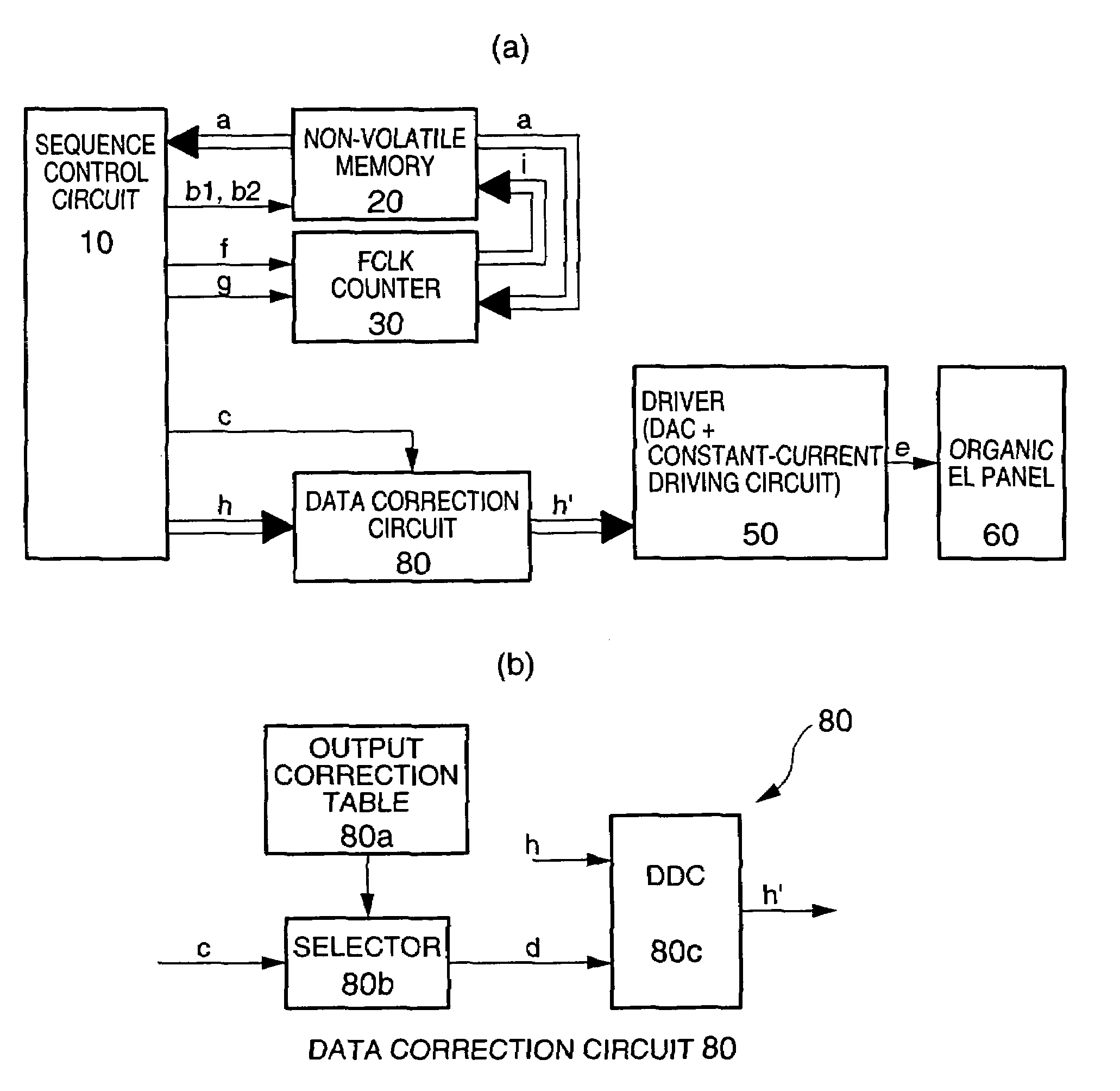
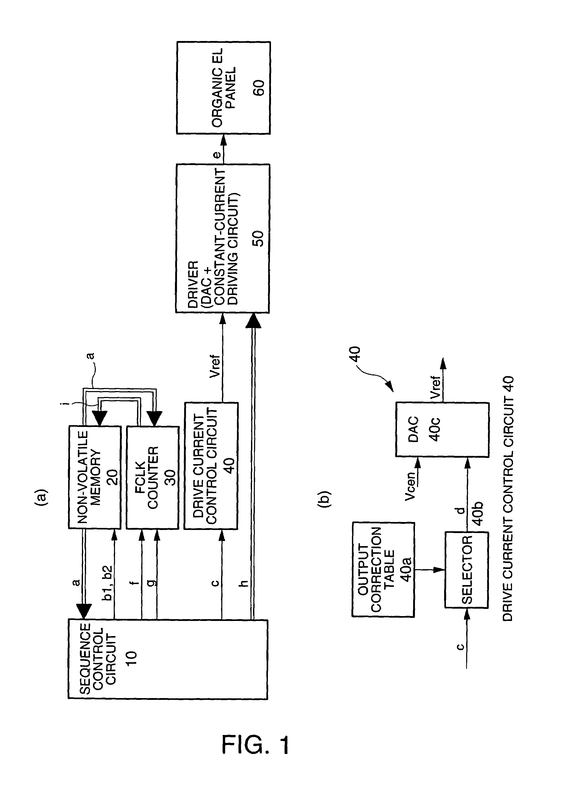
[0036]Specifically, as shown in FIG. 1(a), the organic EL display apparatus according to the first exemplary embodiment includes a sequence control circuit 10, a non-volatile memory 20, such as a flash memory, an FCLK counter 30, a drive current control circuit 40, a driver 50 formed of a well-known DAC (D / A converter) and a constant-current driving circuit, and an organic EL panel 60. As shown in FIG. 1(b), the drive current control circuit 40 includes an output correction table 40a, a selector 40b, and a DAC (D / A converter) 40c.
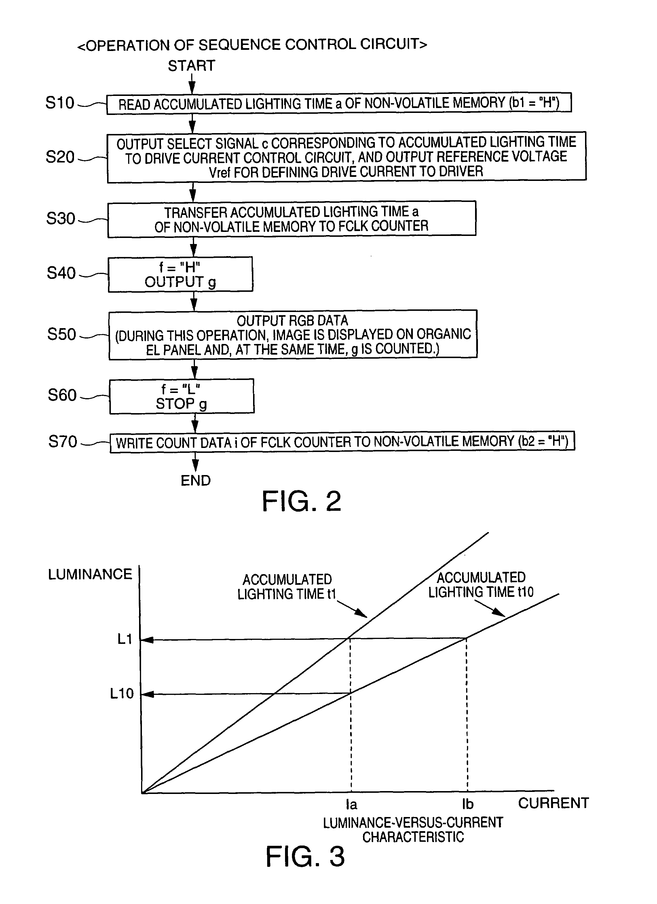
[0037]The operation of the sequence control circuit 10 is described below. As shown in the schematics of FIGS. 1(a) and 1(b), the sequence control circuit 10 reads an accumulated lighting time a stored in the non-volatile memory 20 (this operation corresponds to step S10 ...
second exemplary embodiment
[0044]In the second exemplary embodiment, the total sum of image data described below is counted to estimate the accumulated luminance of the organic EL display apparatus, thereby defining the central voltage of the DAC included in the driver 50. Other portions than this portion are common to those in the aforementioned first embodiment, and therefore the difference therebetween is primarily described below.
[0045]Specifically, as shown in FIG. 4, the organic EL display apparatus according to the second exemplary embodiment includes an RGB counter 31 in place of the FCLK counter 30 shown in FIGS. 1(a) and 1(b). The RGB counter 31 may measure, as the accumulated luminance, the amount of data for at least one of R, G, and B types of electro-optical devices. In the second exemplary embodiment, the RGB counter 31 measures, as the accumulated luminance, the amount of data for all R, G, and B.
[0046]The operation of the sequence control circuit is described below. As shown in the schematic ...
third exemplary embodiment
[0051]In the third exemplary embodiment, image data described below is counted for each of R, G, and B to estimate an accumulated luminance of the organic EL display apparatus. This allows accurate estimation of the accumulated luminance. Other portions than this portion are common to those in the above-described second embodiment, and therefore the difference therebetween is primarily described below.
[0052]Specifically, as shown in FIG. 6, in the organic EL display apparatus of the third exemplary embodiment, the non-volatile memory 20 shown in FIG. 4 is formed of a non-volatile memory 20a for R, a non-volatile memory 20b for G, and a non-volatile memory 20c for B, and the RGB counter 31 shown in FIG. 4 is formed of a counter 31a for R, a counter 31b for G, and a counter 31c for B. Furthermore, the drive current control circuit 40 shown in FIG. 4 is formed of a circuit 41 for R, a circuit 42 for G, and a circuit 43 for B.
[0053]The operation of the sequence control circuit is descri...
PUM
| Property | Measurement | Unit |
|---|---|---|
| luminance | aaaaa | aaaaa |
Abstract
Description
Claims
Application Information
 - R&D
- Intellectual Property
- Life Sciences
- Materials
- Tech Scout
- Unparalleled Data Quality
- Higher Quality Content
- 60% Fewer Hallucinations
Browse by: Latest US Patents, China's latest patents, Technical Efficacy Thesaurus, Application Domain, Technology Topic, Popular Technical Reports.
© 2025 PatSnap. All rights reserved.Legal|Privacy policy|Modern Slavery Act Transparency Statement|Sitemap|About US| Contact US: help@patsnap.com