Multi-stage excitation double-cylinder magnetorheological damper and control method thereof

A magnetorheological damper, dual-tube technology, applied in the direction of shock absorber, shock absorber, liquid shock absorber, etc., to achieve the effect of expanding the range of controllable damping force

Pending Publication Date: 2022-04-29
CHONGQING UNIV
View PDF0 Cites 0 Cited by
  • Summary
  • Abstract
  • Description
  • Claims
  • Application Information

AI Technical Summary

Problems solved by technology

Existing magnetorheological dampers have the limitation that the damping force can only be controlled by changing the magnitude of the current under a specific flow gap

Method used


Image

  • Multi-stage excitation double-cylinder magnetorheological damper and control method thereof
  • Multi-stage excitation double-cylinder magnetorheological damper and control method thereof
  • Multi-stage excitation double-cylinder magnetorheological damper and control method thereof

Examples


Embodiment 1

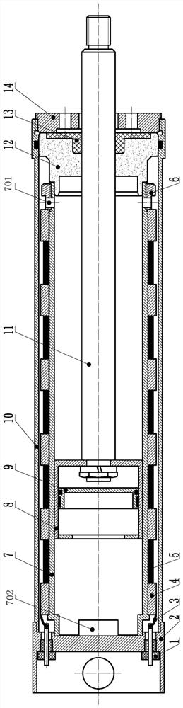
[0032] In view of the limitation that the current magneto-rheological damper can only control the damping force by changing the magnitude of the current under a specific flow gap, this embodiment provides a multi-stage excitation double-tube magnetorheological damper, including a base 2 and an inner tube 7 , an outer cylinder 10, a guide seal assembly, a piston assembly and a magnetic circuit assembly.

[0033] The openings at both ends of the outer cylinder 10 are sealed by a guide sealing assembly and a base 2 respectively. The inner cylinder 7 is coaxially arranged in the outer cylinder 10 . Both ends of the inner cylinder 7 are open against the guide seal assembly and the base 2 respectively. A channel cavity is formed between the outer wall of the inner cylinder 7 and the inner wall of the outer cylinder 10 . A plurality of circulation windows I 701 are opened on the side wall of the inner cylinder 7 close to the end of the guide seal assembly, and a plurality of circul...

Embodiment 2

[0039] The main structure of this embodiment is the same as that of Embodiment 1, wherein, the guide seal assembly includes a guide seat 12 , an oil seal 13 and a pressure plate 14 . One end of the guide seat 12 is in contact with the inner cylinder 7 , and the other end is in contact with the oil seal 13 . An O-ring is arranged on the outer periphery of the guide seat 12 to seal the outer circular surface, and the inner circular surface is sealed by the lip of the oil seal 13 .

Embodiment 3

[0041] The main structure of this embodiment is the same as that of Embodiment 1, wherein, the base 2 has N threaded holes. Injection molded terminals 1 are arranged in the threaded holes. The excitation circuit of each coil 5 is drawn out of the base 2 through the lead wire 3 and the injection molding terminal 1 .


PUM


Abstract

The invention provides a multi-stage excitation double-cylinder magnetorheological damper and a control method thereof. The damper comprises a base, an inner cylinder, an outer cylinder, a guide sealing assembly, a piston assembly and a magnetic circuit assembly. Openings in the two ends of the outer cylinder are plugged through a guide sealing assembly and a base respectively. And the inner cylinder is coaxially arranged in the outer cylinder. And a runner cavity is formed between the outer wall of the inner cylinder and the inner wall of the outer cylinder. The magnetic circuit assembly is arranged in the flow channel cavity. And when the coil is electrified, the circulation channel I adjacent to the coil is converted into an active flow gap. Positive electrodes of the (N-1) coils are independently led out from the base. And the (N-1) coils share the negative electrode. And the negative electrodes of the (N-1) coils are connected in parallel and then are led out from the base. The constant voltage source excites the coil. According to the damper, the controllable damping force range of the magnetorheological damper is greatly expanded. The magnitude of the damping force is controlled by controlling the number of the active flow gaps by adjusting and controlling the applied magnetic field, and combination of different damping force control ranges is achieved.

Description

technical field [0001] The invention relates to the field of vibration and buffer active control, in particular to a multi-stage excitation double-tube magneto-rheological damper and a control method thereof. Background technique [0002] Magneto Rheological Fluid (MRF for short) is a suspended liquid with controllable apparent viscosity under the action of an external magnetic field. The magnetorheological effect is randomly regulated according to the change of the intensity of the external magnetic field. Magnetorheological fluid is an important part of smart materials, and its research and application have attracted great attention from researchers all over the world. [0003] The magnetorheological damper is a device carrier for magnetorheological fluid applications. The damping force is regulated by an external (current) magnetic field. It has a wide range of application values ​​in the fields of automobile manufacturing, measurement technology, and machining. Compare...

Claims


Application Information

Patent Timeline
Patent Type & Authority Applications(China)
IPC IPC(8): F16F9/16F16F9/53F16F9/50F16F9/32
CPCF16F9/16F16F9/535F16F9/50F16F9/3221F16F9/3214F16F9/3207
Inventor 张红辉熊苧淞安娜邹致远
Owner CHONGQING UNIV
Why Eureka
Try Eureka