
Dosing device

A technology of dosing device and silo, which is applied in neutralizing water/sewage treatment, process efficiency improvement, metallurgical wastewater treatment, etc., and can solve problems such as failure of dosing device, inaccurate control of chemical concentration, high failure rate of equipment, etc.

Pending Publication Date: 2022-04-29
铜陵有色金属集团股份有限公司
View PDF0 Cites 0 Cited by
  • Summary
  • Abstract
  • Description
  • Claims
  • Application Information

AI Technical Summary

Problems solved by technology

[0003] 1. The demand for dosing amount fluctuates greatly, and the control of chemical concentration is inaccurate: the pH of water quenching water is determined by the grade and sulfur content of copper concentrate. In view of the current domestic ore and imported mines, the grade fluctuates greatly, and the original dosing method is very difficult. It is difficult to accurately and efficiently control the pH of water quenching water, and in addition, it is impossible to adjust in time according to the water quality through manual timing and quantitative addition of chemicals;
[0004] 2. High failure rate of equipment: The dosing pump adopts a diaphragm structure, which requires high cleanliness of the solution. Impurities and foreign matter will cause failure of the dosing device, high shutdown rate, and high maintenance and spare parts costs. No less;
[0005] 3. The level of environmental protection control is low: in the past, chemicals were manually added to the mixing tank, and there were no effective control measures for the flying of drug dust, which had a certain impact on personnel health and the environment

Method used


Image

  • Dosing device

Examples


Embodiment Construction

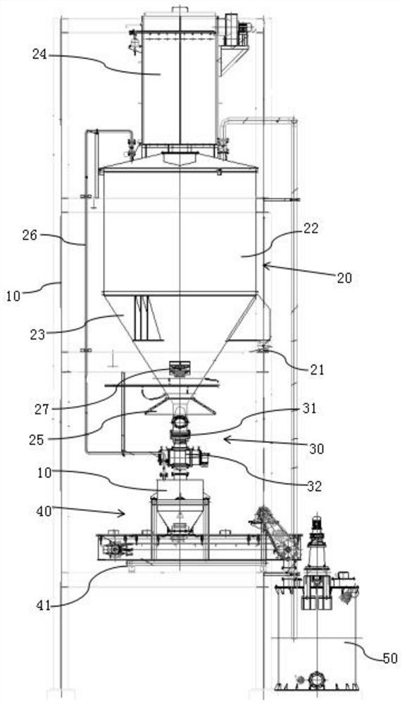
[0010] Such as figure 1 As shown, a dosing device is provided with a feed bin 20 on the frame 10, a discharge valve unit 30 is provided at the outlet of the feed bin 20, and a buried scraper conveyor 40 is provided below the discharge valve unit 30. The discharge end of the plate conveyor 40 is connected with the mixing barrel 50, and the bin 20 and the buried scraper conveyor 40 are respectively provided with a bin weighing unit 21 and a conveying weighing unit 41, and the bin weighing unit 21 monitors the material in real time. The weight of the medicament in the bin and transmit the signal to the control unit, the control unit controls feeding to the silo 20 or stops the feeding, and the conveying weighing unit 41 collects the amount of medicine on the buried scraper conveyor 40 and transmits the signal to the control unit unit, the control unit controls the rotational speed of the servo motor of the buried scraper conveyor 40 . The medicine is transported to the silo 20 t...


PUM


Abstract

The invention aims to provide a dosing device capable of accurately controlling metering and guaranteeing long-period stable operation of equipment, a discharge valve unit is arranged at an outlet of a stock bin, an embedded scraper transporter is arranged below the discharge valve unit, the discharge end of the embedded scraper transporter is connected with a stirring barrel, and the discharge end of the embedded scraper transporter is connected with the stirring barrel. A stock bin weighing unit and a conveying weighing unit are arranged below the stock bin and the embedded scraper transporter respectively, the stock bin weighing unit monitors the weight of chemicals in the stock bin in real time and transmits a signal to the control unit, and the control unit controls feeding of the stock bin or stopping of feeding. The conveying and weighing unit collects the dosage of chemicals on the embedded scraper transporter and transmits a signal to the control unit, and the control unit controls the rotating speed of a servo motor of the embedded scraper transporter. Automatic dosing is achieved through the stock bin and the embedded scraper transporter, the stock bin weighing unit controls the loading amount, coarse metering of large weight is achieved, the conveying weighing unit controls the output amount, fine metering of small conveying amount is achieved, and accurate conveying is guaranteed due to the mutual correlation between the stock bin weighing unit and the conveying weighing unit.

Description

technical field [0001] The invention relates to the technical field of copper smelting equipment, in particular to a dosing device. Background technique [0002] At present, in the copper flash smelting industry, the matte separated from the smelting furnace flows into the matte water quenching system through the chute on a regular basis. The water quenching system is equipped with granulation, dehydration, transportation, sedimentation, dosing and cooling devices. The melt is granulated to form solid matte particles with a particle size of less than 5mm and discharged to the water quenching pool. The mixture of matte and water is dehydrated and taken out by a bucket elevator, and then transported to the matte yard through a belt. The water in the water quenching pool overflows. Flow to the sedimentation tank, then add lye (usually lime) to the sedimentation tank to adjust the pH value in the tank, the bottom flow after sedimentation is sent back to the water quenching tank ...

Claims


Application Information

Patent Timeline
Patent Type & Authority Applications(China)
IPC IPC(8): C02F1/66C22B15/00C02F103/16
CPCC02F1/66C22B15/0047C02F2103/16Y02P10/20
Inventor 席光耀张文强马彪张凌志马骁许强
Owner 铜陵有色金属集团股份有限公司
Learn More