Fabricated roller thrust ring and manufacturing method thereof

A manufacturing method and thrust ring technology, which is applied in the field of metallurgical equipment parts, can solve problems affecting turning speed, processing efficiency, and sealing surface grinding, so as to improve processing efficiency and surface quality, save costs and time, and reduce The effect of processing difficulty

Pending Publication Date: 2022-04-29
SINOSTEEL XINGTAI MACHINERY & MILL ROLL
View PDF0 Cites 0 Cited by
  • Summary
  • Abstract
  • Description
  • Claims
  • Application Information

AI Technical Summary

Problems solved by technology

Generally, it is produced by integral casting or forging, but due to its large volume, complex shape, and large blank-to-net ratio, it is difficult to produce blanks by casting and forging, and the deep ring groove on its structure also makes processing difficult. The processing is too long, too heavy, and the clamping is firm and unsafe. It is difficult to process deep grooves on the vertical lathe to discharge iron chips and affect the processing efficiency; at the same time, the turning tool protrudes too long during deep groove processing, which is very easy to vibrate, resulting in turning vibration marks , affects the turning speed, and the groove side also affects the grinding of the sealing surface
In view of the above reasons, the production cycle of large roll thrust rings is particularly long, which often affects the delivery cycle of rolls

Method used


Image

  • Fabricated roller thrust ring and manufacturing method thereof
  • Fabricated roller thrust ring and manufacturing method thereof
  • Fabricated roller thrust ring and manufacturing method thereof

Examples


Embodiment Construction

[0027] The technical solution of the present invention will be described in detail below in conjunction with specific embodiments

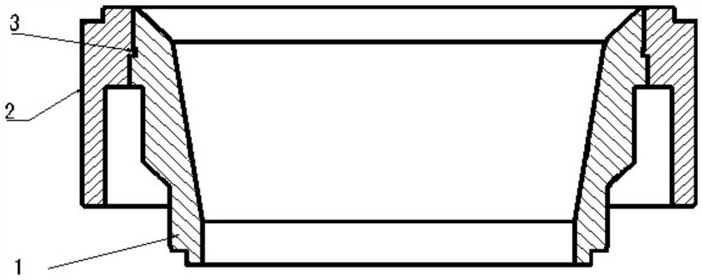
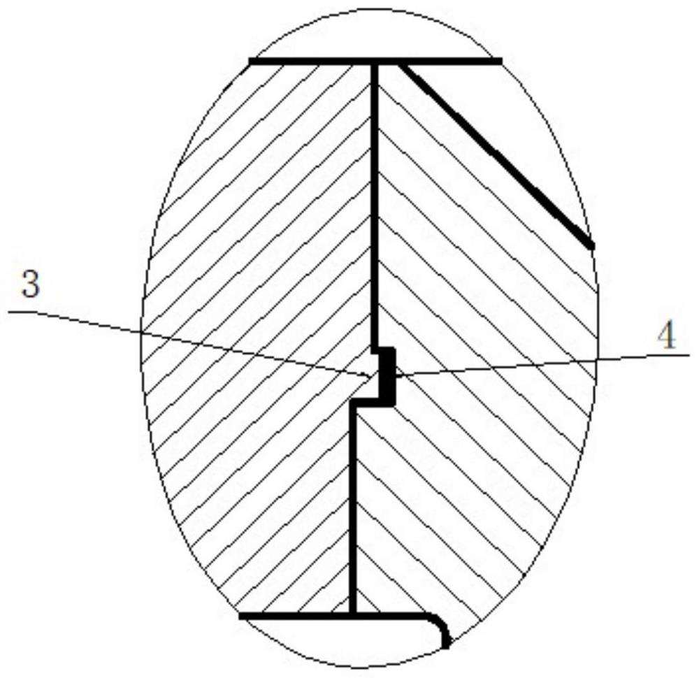
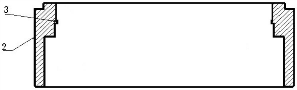
[0028] A large roll thrust ring such as Figure 1-4 As shown, it includes an overcoat 2 and an inner cover 1, the overcoat 2 is barrel-shaped, and its cross section is a door shape. The inner shoulder of the overcoat 2 is provided with a step platform one, and the inner diameter of the upper part of the step platform one is smaller than the inner diameter of the lower part, and The step of step platform 1 is provided with a boss 3, the inner sleeve 1 is a trapezoidal barrel-shaped structure, the outer wall is provided with multiple irregular steps, the outer shoulder of the inner sleeve 1 is provided with a step platform 2, and the upper part of the step platform 2 The outer diameter is smaller than the outer diameter of the lower part, and the step of the step platform 2 is provided with a slot 4. After the outer sleeve 2 and the inner sleeve 1 a...


PUM

PropertyMeasurementUnit
heightaaaaaaaaaa
depthaaaaaaaaaa
diameteraaaaaaaaaa

Abstract

The invention discloses an assembly type roller thrust ring and belongs to the field of metallurgical equipment parts, the assembly type roller thrust ring comprises an outer sleeve and an inner sleeve, the outer sleeve is in a barrel shape, the cross section of the outer sleeve is in a door shape, a first step table is arranged on the shoulder of the inner side of the outer sleeve, the inner diameter of the upper portion of the first step table is smaller than that of the lower portion of the first step table, and a boss is arranged at the step of the first step table; the inner sleeve is of a trapezoidal barrel-shaped structure, multiple stages of irregular steps are arranged on the outer side wall of the inner sleeve, a second step table is arranged on the shoulder portion of the outer side of the inner sleeve, the outer diameter of the upper portion of the second step table is smaller than that of the lower portion of the second step table, and clamping grooves are formed in the steps of the second step table. And the boss is engaged with the clamping groove. According to the thrust ring, the ring which is large in weight and complex in structure is divided into two small rings which are small in weight and simple in structure, the blank amount of the deep ring groove is reduced, and therefore the rough net ratio of the blank of the thrust ring is reduced, machining is convenient, and cost and time are saved.

Description

technical field [0001] The invention belongs to the field of metallurgical equipment parts, and in particular relates to an assembled roll thrust ring and a manufacturing method thereof. Background technique [0002] Due to the large diameter of the roll body of the rough rolling large vertical roll of the hot strip mill, the thrust rings assembled at both ends are also relatively huge, especially the outer diameter of the thrust ring at the lower end is φ1050-1100mm, the length is 390-460mm, and the unit weight is 0.9-1.15 tons. The end face also has a ring groove with a width of 65mm and a depth of 175-215mm. Generally, it is produced by integral casting or forging, but due to its large volume, complex shape, and large blank-to-net ratio, it is difficult to produce blanks by casting and forging, and the deep ring groove on its structure also makes processing difficult. The processing is too long, too heavy, and the clamping is firm and unsafe. It is difficult to process d...

Claims


Application Information

Patent Timeline
Patent Type & Authority Applications(China)
IPC IPC(8): B21J5/02
CPCB21J5/02
Inventor 何彦杰
Owner SINOSTEEL XINGTAI MACHINERY & MILL ROLL
Why Eureka
Try Eureka