Car lamp driving circuit and driving method thereof

A driving circuit and driving method technology, applied in the application of electrical components, semiconductor lamps, energy-saving control technology, etc., can solve problems such as damage, overheating of the lamp and its driving circuit, avoid high temperature damage, simple structure and low cost Effect

Pending Publication Date: 2022-04-26
SHANGHAI NATLINEAR ELECTRONICS CO LTD +1
View PDF6 Cites 0 Cited by
  • Summary
  • Abstract
  • Description
  • Claims
  • Application Information

AI Technical Summary

Problems solved by technology

[0005] In view of the above-mentioned shortcomings of the prior art, the purpose of the present invention is to provide a car lamp driving circuit and its driving method, which is used to solve the problem of overheating of the car lamp and its driving circuit caused by the inability to detect fan failures in the existing car lamp driving circuit. And the problem of damage

Method used


Image

  • Car lamp driving circuit and driving method thereof
  • Car lamp driving circuit and driving method thereof
  • Car lamp driving circuit and driving method thereof

Examples


Embodiment Construction

[0051] Embodiments of the present invention are described below through specific examples, and those skilled in the art can easily understand other advantages and effects of the present invention from the content disclosed in this specification. The present invention can also be implemented or applied through other different specific implementation modes, and various modifications or changes can be made to the details in this specification based on different viewpoints and applications without departing from the spirit of the present invention.

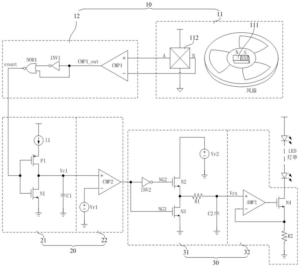
[0052] see Figure 2 to Figure 4 . It should be noted that the diagrams provided in this embodiment are only schematically illustrating the basic idea of ​​the present invention, so that only the components related to the present invention are shown in the diagrams rather than the number, shape and Dimensional drawing, the type, quantity and proportion of each component can be changed arbitrarily during actual implementation, and the c...


PUM


Abstract

The invention provides a vehicle lamp driving circuit and a driving method thereof, and the circuit comprises a rotating speed detection unit which is used for detecting the rotating speed of a fan, and correspondingly generating narrow pulse signals with different periods based on the rotating speed of the fan; the over-threshold time adjusting unit is connected with the output end of the rotating speed detection unit and is used for adjusting the time when the voltage value exceeds a set threshold according to the period of the narrow pulse signal and adjusting the duty ratio of an output control signal; and the driving adjusting unit is connected with the output end of the over-threshold time adjusting unit and is used for adjusting the driving voltage according to the duty ratio of the control signal and adjusting the current flowing through the LED vehicle lamp, so that the current flowing through the LED vehicle lamp is changed in a positive correlation manner along with the change of the rotating speed of the fan. According to the automobile lamp driving circuit and the driving method thereof, the problem that the automobile lamp and the driving circuit thereof are damaged due to overheating caused by the fact that an existing automobile lamp driving circuit cannot detect fan faults is solved.

Description

technical field [0001] The invention belongs to the field of circuit design, in particular to a car lamp driving circuit and a driving method thereof. Background technique [0002] The application of LED on car lights is more and more extensive. The existing LED car lights are usually sealed in the car body. The greater the power of LED car lights, the more prominent the problem of heat dissipation. In order to dissipate heat, LED car lights are generally equipped at the rear There is a radiator, and a fan is arranged in the radiator, and the temperature of the LED car light is cooled by the fan. [0003] Such as figure 1 As shown, the existing LED drive circuit and the fan work independently, and there is no electrical connection between them; the LED drive circuit uses the amplifier AMP0, the NMOS tube N0 and the resistor R0 to form a negative feedback structure to provide constant current drive for the LED light string; The fan is generally located at the tail of the he...

Claims


Application Information

Patent Timeline
Patent Type & Authority Applications(China)
IPC IPC(8): H05B47/105H05B45/30H05B45/34H05B45/345H05B45/315
CPCH05B47/105H05B45/30H05B45/34H05B45/345H05B45/315Y02B20/30Y02B20/40
Inventor 夏虎刘桂芝王冬峰吴春达
Owner SHANGHAI NATLINEAR ELECTRONICS CO LTD
Why Eureka
Try Eureka