Flexible multi-station continuous clamping device and method

A clamping device and multi-station technology, used in packaging, packaging cigarettes, etc., can solve the problems of inability to adjust, random stop position of workpiece, lack of clamping force, etc., to reduce cycle time and improve work stability. , The effect of simple and compact structure

Inactive Publication Date: 2022-04-26
云南烟草机械有限责任公司
View PDF0 Cites 0 Cited by
  • Summary
  • Abstract
  • Description
  • Claims
  • Application Information

AI Technical Summary

Problems solved by technology

[0003] Most of the existing step-by-step multi-station production lines are realized by lug synchronous belts or intermittent push mechanisms, which inevitably lead to the lack of clamping force when the target workpiece is under the action of unidirectional force, so that the stop position of the workpiece is random. Uncertainty affects production efficiency and product stability, so it is necessary to set up a clamping device separately to ensure that the workpiece stops at the same position. At present, some multi-station production lines have been equipped with a clamping mechanism. The existing problems of the clamping mechanism are: 1. The components of these clamping mechanisms cannot be adjusted, so they can only be applied to workpieces of a certain specification, and cannot be applied to different station intervals, nor can they meet different product specifications and sizes, and these clamping mechanisms are often not compact enough.
2. The positions of these clamping mechanisms are fixed, and can only complete the action of clamping and loosening the workpiece, which makes it inevitable that the workpiece will stop while clamping the workpiece. After the clamping mechanism is released, the workpiece can be Continue to move downstream, unable to achieve continuous work of the workpiece

Method used


Image

  • Flexible multi-station continuous clamping device and method
  • Flexible multi-station continuous clamping device and method
  • Flexible multi-station continuous clamping device and method

Examples


Embodiment 1

[0065] This example is mainly used in the step-by-step production line, where the workpiece cannot be clamped during transportation, but it needs to be positioned and clamped when it is transported to the action station.

[0066] See Figure 5 (clamping state), the workpiece is transported by the conveyor belt 12 into the clamping station, the workpiece is pushed forward by the lug 13 on the conveyor belt, and is transported to the clamping station, and the positioning of the workpiece is completed by the clamping device and the lug and clamping (see Figure 5 ). In the example, the distance between the stations is M, that is, the distance between the clamping movable plates in the clamping device is M, and the distance between the lugs of the conveyor belt is also M. The two phases cooperate to complete the simultaneous clamping of multiple stations; for the distance L of the clamped workpiece The adjustment can be realized in two ways. One is to control the vertical displace...


PUM


Abstract

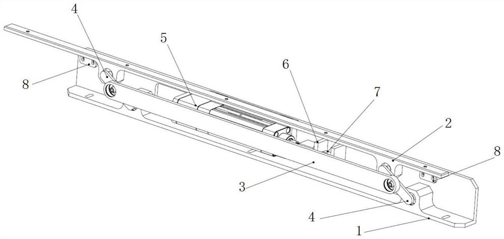
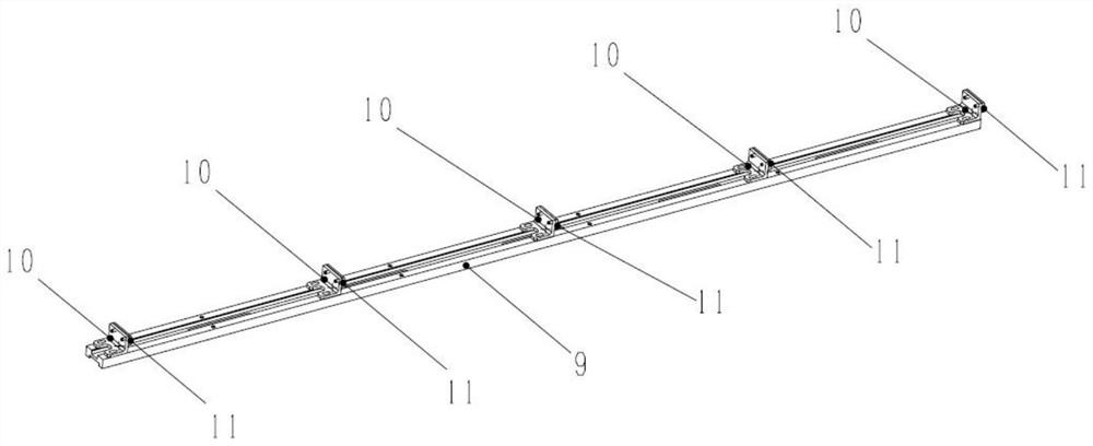
The invention discloses a flexible multi-station continuous clamping device. The flexible multi-station continuous clamping device comprises a four-connecting-rod base assembly (N1) and a movable clamping assembly (N2). The movable clamping assembly (N2) is located on the four-connecting-rod base assembly (N1), and the four-connecting-rod base assembly (N1) drives the movable clamping assembly (N2) to move along an arc track so as to generate displacement in the vertical direction and the horizontal direction at the same time. The movable clamping assembly (N2) comprises a plurality of clamping movable plates (10). Different station intervals can be rapidly achieved, clamping of different product specifications and sizes can be met, the requirement for continuity of product production is met while the flexible production requirement is met, the structure is simple and compact, the clamping device can be installed in a conveying channel, operation of other installation stations is not affected, application of a four-connecting-rod mechanism is not affected, and the production efficiency is improved. The working stroke of the electric cylinder is reduced, space is saved, and the working stability of the clamping device is improved.

Description

technical field [0001] The invention belongs to the field of packaging, and in particular relates to a flexible multi-station continuous clamping device and method. Background technique [0002] With the development and progress of the cigarette food industry, the packaging of cigarette products is becoming more and more diversified, and cigarette products with various special-shaped packages emerge in an endless stream, and the packaging methods are also becoming more and more diversified. Among them, the step-by-step multi-station flow production line It is an important one in various production lines. [0003] Most of the existing step-by-step multi-station production lines are realized by lug synchronous belts or intermittent push mechanisms, which inevitably lead to the lack of clamping force when the target workpiece is under the action of unidirectional force, so that the stop position of the workpiece is random. Uncertainty affects production efficiency and product ...

Claims


Application Information

Patent Timeline
IPC IPC(8): B65B19/04B65B59/00
CPCB65B19/04B65B59/001B65B59/005
Inventor 杨潇李宏彬李刘平杨振刘瑶马龙李少鹏张新蒲凤康王兵
Owner 云南烟草机械有限责任公司
Why Eureka
Try Eureka