Fuel supply structure of vane type internal combustion engine

A fuel supply, internal combustion engine technology, applied in the direction of internal combustion piston engines, combustion engines, mechanical equipment, etc., can solve the problems of rising costs and unexplained details, and achieve the effect of simple structure

Inactive Publication Date: 2015-09-16
中川 宗司
View PDF7 Cites 0 Cited by
  • Summary
  • Abstract
  • Description
  • Claims
  • Application Information

AI Technical Summary

Problems solved by technology

[0003] However, the fuel nozzle is operated by a solenoid, and the direct injection fuel nozzle uses a high-pressure fuel pump or a piezoelectric element, so the cost increases
[0004] The fuel supply structure of the vane-type internal combustion engine that is currently proposed can only be inferred from the name of the injector or fuel nozzle, and its specific content is not explained at all.

Method used


Image

  • Fuel supply structure of vane type internal combustion engine
  • Fuel supply structure of vane type internal combustion engine
  • Fuel supply structure of vane type internal combustion engine

Examples


Embodiment Construction

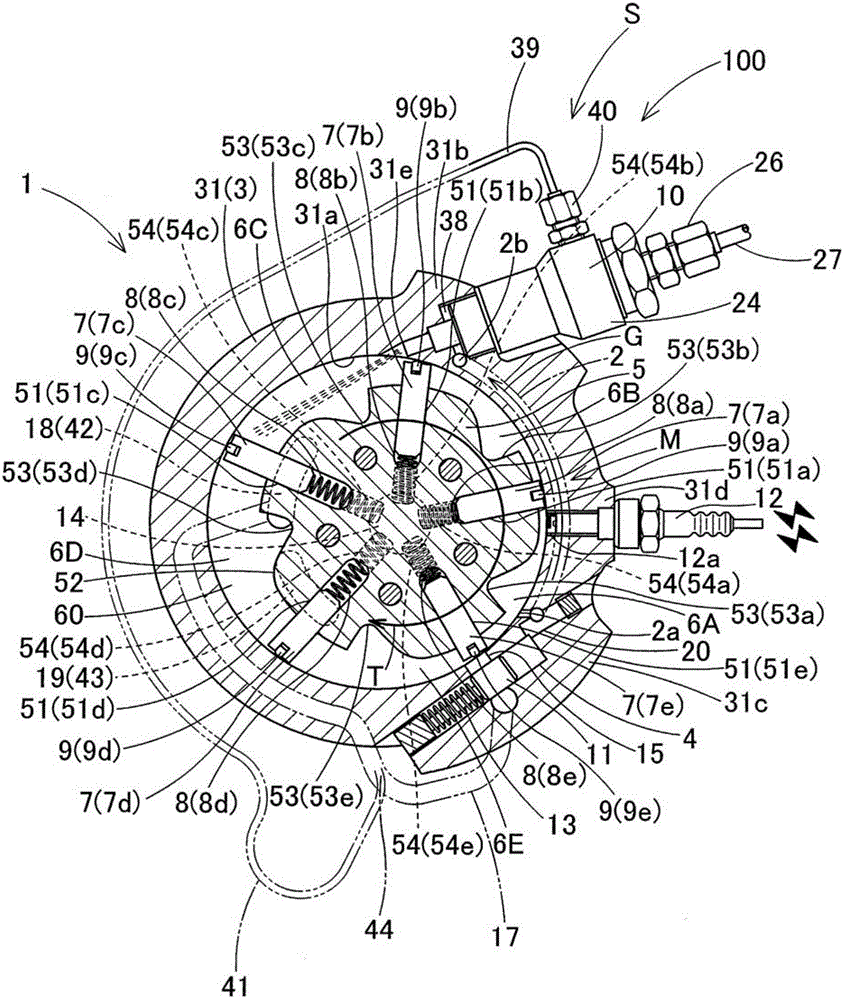
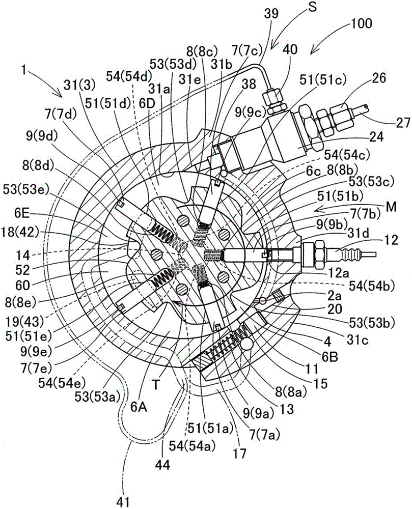
[0032] One embodiment of the fuel supply structure of the vane type internal combustion engine according to the present invention will be described with reference to the drawings. The fuel supply structure (hereinafter referred to as "fuel supply structure") 100 of the vane type internal combustion engine of the present invention solves the problem that the fuel nozzle stops due to the failure of the electrical system.

[0033] The vane type internal combustion engine (hereinafter referred to as "engine") 1 having the fuel supply structure 100 of the embodiment is configured to sequentially repeat explosion, expansion, exhaust, air intake, air compression, supercharging, and scavenging in one cycle. , Compressed air intake, mixed gas compression stroke.

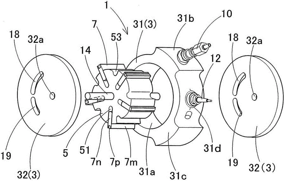
[0034] engine 1 as image 3 As shown, there is: a housing 3, which has a substantially cylindrical housing body portion 31 and a pair of side housing portions 32, 32, which are disposed on the sides of the housing body porti...


PUM


Abstract

The invention provdies a fuel feeding structre of a blade type internal combustion engine, which prevents a fuel nozzle from being stopped due to the fault of an electrical system with a simple structure. The part of a housing main body part (31), facing the areas of the explosive stroke and the expansion stroke is communicated with the fuel nozzle (10) to form an explosion pressure transmission path (2). The high-pressure combustion gases G generated during the explosive stroke flow in through the explosion pressure transmission path (2) and is conveyed to the fuel nozzle (10) to enable a plunger (23) configured in the fuel nozzle (10) to move, thereby injectng the fuel.

Description

technical field [0001] The present invention relates to a fuel supply structure of a vane-type internal combustion engine, and aims to simply and efficiently supply fuel to intake air by utilizing the impact pressure of explosive combustion gas and the flow of pressurized gas of the vane-type internal combustion engine. Background technique [0002] As an item that greatly affects the performance of the internal combustion engine (engine), the intake efficiency of air and fuel in the intake stroke is a major factor. In existing engines, fuel is supplied using a carburetor, fuel nozzles, or direct injection fuel nozzles. However, since fuel regulation in carburetors is strongly influenced by the intake air, fuel nozzles were gradually used instead. In addition, for the purpose of exhaust purification and fuel consumption rate or output improvement, due to the fuel supply amount or the timing is favorable, it is gradually switched to the use of direct injection fuel nozzles. ...

Claims


Application Information

Patent Timeline
Patent Type & Authority Patents(China)
IPC IPC(8): F02B53/10
CPCY02T10/17Y02T10/12
Inventor 中川宗司
Owner 中川 宗司
Why Eureka
Try Eureka