
Roll changing and material receiving mechanism of film blowing machine

A material receiving mechanism and film blowing machine technology, applied in the direction of winding strips, thin material processing, flat products, etc., can solve the problems of low production efficiency and achieve the effect of convenient roll changing

Pending Publication Date: 2022-03-25
德清县康福塑料制品有限公司
View PDF0 Cites 0 Cited by
  • Summary
  • Abstract
  • Description
  • Claims
  • Application Information

AI Technical Summary

Problems solved by technology

[0006] The invention provides a film blowing machine rewinding and rewinding mechanism, one of the purposes of which is to facilitate the reversing and dismantling of the rewinding roller, and solve the need for the rewinding mechanism to turn the machine when the rewinding shaft is full of a roll of material. Stop and manually disassemble and remove the rewinding shaft and then replace it with a new rewinding shaft to reinstall the problem of low production efficiency; another purpose is to solve the problem that the plastic film needs to be cut off when the rewinding mechanism is changing rolls. The problem that it needs to be manually picked up and glued to the new take-up roller to achieve the effect of automatically cutting off the transition

Method used


Image

  • Roll changing and material receiving mechanism of film blowing machine
  • Roll changing and material receiving mechanism of film blowing machine
  • Roll changing and material receiving mechanism of film blowing machine

Examples


Embodiment 1

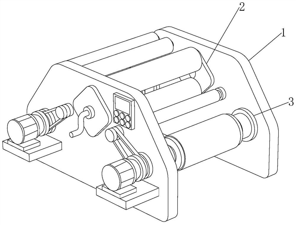
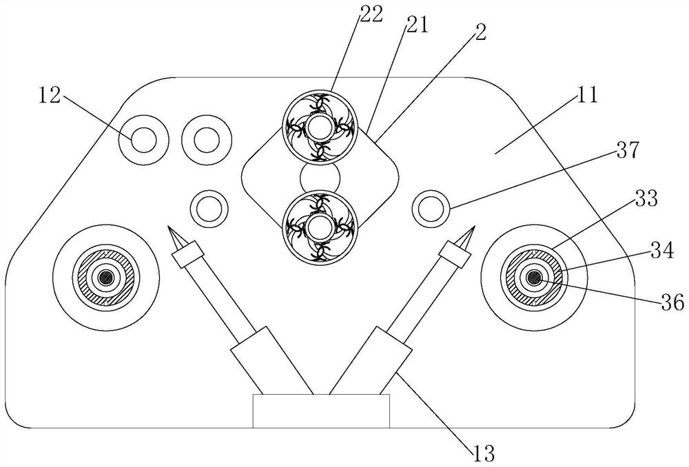
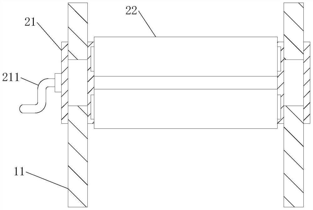
[0034] like Figure 1-9 As shown, the present invention provides a roll changing and receiving mechanism for a film blowing machine, including a roll changing and receiving mechanism main body 1, and the roll changing and receiving mechanism main body 1 includes a mechanism frame 11, and a film feeding roller is movably installed at the front end of the mechanism frame 11 12. The lower end of the mechanism frame 11 is provided with a cutting device 13, one side of the film feeding roller 12 is provided with a roll-changing guide mechanism 2, and the lower end of the roll-changing guide mechanism 2 is provided with a receiving device 3, and the roll-changing guide mechanism 2 includes The reversing frame 21 and the film guide roller 22, the surface of the reversing frame 21 is movably connected with the inner wall of the mechanism frame 11, and the receiving device 3 includes a motor 31, a driving pulley 32, a receiving roller installation sleeve 33, and a receiving roller 34 ,...

Embodiment 2

[0037] like Figure 1-9 As shown, on the basis of Embodiment 1, the present invention provides a technical solution: the outer surface of the fixed shaft 221 is movably connected with the inner surface of the movable sleeve 222, and a rubber plate 2221 is arranged between the movable sleeve 222 and the membrane guide sleeve 223 , both sides of the rubber plate 2221 are movably equipped with a rotating rod 2222, and one end of the rotating rod 2222 is fixedly connected with the surface of the guide film sleeve 223 and the movable sleeve 222 respectively, and the two ends of the rubber plate 2221 are fixedly installed with a spring connecting rod 2223, and the spring is connected One end of the rod 2223 is hinged to the surfaces of the guide membrane sleeve 223 and the movable sleeve 222 respectively.

[0038] In this embodiment, the fixed shaft 221 and the movable sleeve 222 cooperate with each other to make the guide film sleeve 223 rotate to reduce the friction between the pl...

Embodiment 3

[0040] like Figure 1-9As shown, on the basis of Embodiment 1, the present invention provides a technical solution: the output end of the motor 31 is fixedly connected to one end of the driving pulley 32, a driven pulley 321 is arranged above the driving pulley 32, and the driving pulley 32 The other end of wheel 32 and driven pulley 321 is movably connected with the inwall of mechanism frame 11, belt 322 is movably installed between driven pulley 321 and driving pulley 32, and the outer surface of receiving roller mounting sleeve 33 is connected with driving belt. The side surface of the wheel 32 is fixedly connected, the inner surface of the receiving roller installation sleeve 33 is provided with a socket adapted to the receiving roller 34, the inner wall of the receiving roller installation sleeve 33 is provided with a block, and the outer surface of the receiving roller 34 A card slot is provided, and the outer surface of the receiving roller 34 is movably connected with ...


PUM


Abstract

The invention discloses a roll changing and material receiving mechanism of a film blowing machine, and relates to the technical field of film blowing machines, the roll changing and material receiving mechanism comprises a roll changing and material receiving mechanism main body, the roll changing and material receiving mechanism main body comprises a mechanism frame, the front end of the mechanism frame is movably provided with a film feeding roller, and the lower end of the mechanism frame is provided with a cutting device. By installing the roll changing guide mechanism, a film produced by a film blowing machine is conveyed to the roll changing guide mechanism through the film feeding roller, the film guiding roller plays a role in guiding the film, and the fixed shaft and the movable sleeve are matched with each other to enable the film guiding sleeve to rotate to reduce the friction force between the film guiding sleeve and the plastic film; a rubber plate, a rotating rod and a spring connecting rod are matched with one another to play a role in enabling a film guide sleeve to have elastic force and buffer tension, the situation that a plastic film is broken due to too large tension is avoided, when roll replacement is needed, a handle is rotated, a reversing frame rotates by a certain angle, the output direction of the plastic film is changed to the other side under the action of a film guide roller, roll replacement is convenient, and the production efficiency is improved. The problem that the machine needs to be stopped when the receiving roller is replaced is solved.

Description

technical field [0001] The invention relates to the technical field of film blowing machines, in particular to a film blowing machine rewinding and rewinding mechanism. Background technique [0002] The film blowing machine is a special equipment for producing plastic film. The plastic film needs to be rewound through the rewinding mechanism from blowing out to forming a roll. Therefore, it is necessary to use the film blowing machine to change the rewinding mechanism. [0003] There are following problems at prior art: [0004] 1. In the prior art, the receiving mechanism needs to stop the machine after the receiving shaft is full of a roll of material, and then manually remove the receiving shaft and replace it with a new receiving shaft for reinstallation. Low efficiency and high labor intensity; [0005] 2. In the prior art, the plastic film of the receiving mechanism needs to be cut off when the roll is changed, and then it needs to be manually picked up and glued to ...

Claims


Application Information

Patent Timeline
IPC IPC(8): B65H19/30B65H23/26B65H23/188B65H19/28B65H75/28B65H18/02B29C55/28B29L7/00
CPCB65H19/30B65H23/26B65H23/1888B65H19/28B65H75/28B65H18/021B29C55/28B29L2007/00B65H2701/1133
Inventor 吴建平
Owner 德清县康福塑料制品有限公司
Learn More