Switch cabinet with separated switching function and operating function

An operation function and switchgear technology, applied in the field of switchgear, can solve the problems of heavy equipment overall quality, shortened service life, poor use effect, etc., and achieve the effect of prolonging service life and convenient and effective adjustment.

Inactive Publication Date: 2022-04-22
中科瑞能电气股份有限公司
View PDF1 Cites 0 Cited by
  • Summary
  • Abstract
  • Description
  • Claims
  • Application Information

AI Technical Summary

Problems solved by technology

Compared with the prior art, the switchgear of the present invention has the advantages of convenient lighting, long service life of lighting equipment, real-time monitoring of the condition inside the cabinet, ventilation and dust prevention, and the patent is directly connected with the outside during the actual heat dissipation process, thereby making the inside of the equipment easy to The accumulation of dust makes the internal power functional components susceptible to the influence of the external humid environment, which shortens the actual service life of the equipment. At the same time, due to the limitation of its own structure, it is impossible to conveniently maintain and replace the internal functional components when the internal functional components of the equipment are abnormal, making the equipment The actual use effect is not good. At the same time, the overall quality of the equipment after installation is relatively heavy, so that the equipment cannot be conveniently and effectively adjusted the use position again.

Method used


Image

  • Switch cabinet with separated switching function and operating function
  • Switch cabinet with separated switching function and operating function
  • Switch cabinet with separated switching function and operating function

Examples


Embodiment 1

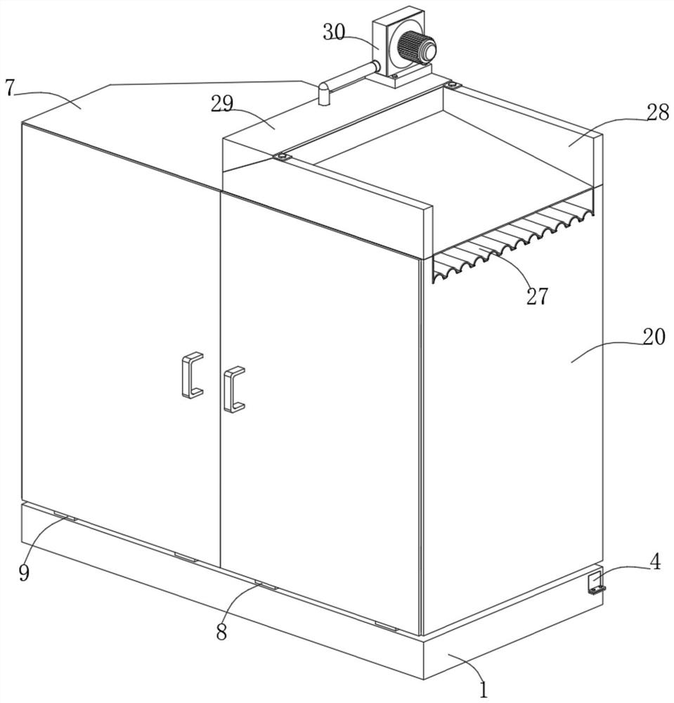
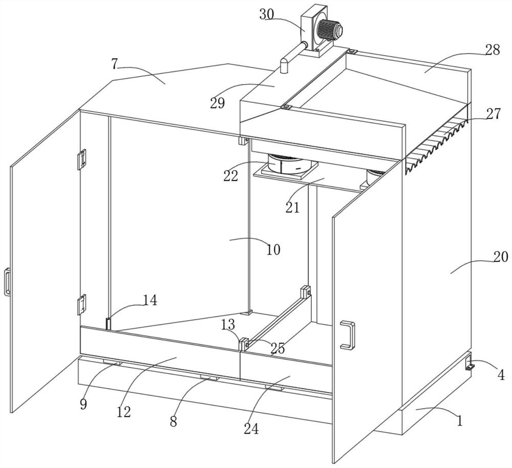
[0036] Embodiment one, with reference to Figure 1-13 : Switchgear with separate switching function and operating function, including a supporting mechanism 1, a switching mechanism 6, an operating mechanism 19 and a heat dissipation mechanism 26, the switching mechanism 6 is arranged on the top of the supporting mechanism 1, and the operating mechanism 19 is also arranged on the top of the supporting mechanism 1 for heat dissipation The mechanism 26 is arranged on the top of the operating mechanism 19. The switch mechanism 6 is provided with a positioning mechanism 14 inside. The positioning mechanism 14 includes a reset frame 15, a slide bar 16, a card 17 and a support spring 18. The slide bar 16 is fixed at the center of the inner bottom surface of the reset frame 15. , the card 17 is slidably sleeved on the outer surface of the slide bar 16, the support spring 18 is slidably sleeved on the outer surface of the slide bar 16, and the support spring 18 is arranged above the ca...

Embodiment 2

[0037] Embodiment two, refer to Figure 4-13 : The outer surface of one side of the limiting frame 4 is fixedly connected with the first connecting piece near the edge of the bottom, the establishment of the first connecting piece cooperates with the second connecting piece and the fixing bolt to effectively limit the use position of the limiting frame 4, and the second There are first threaded holes on both sides of the center of the top of a connecting piece. The establishment of the first threaded hole cooperates with the second threaded hole to effectively install and set the fixing bolts. The outer surface of one side of the bottom frame 2 is located below the corresponding installation port for fixed connection There is a second connecting piece, and second threaded holes are opened on both sides of the top center of the second connecting piece, and fixing bolts are screwed between the inside of each second threaded hole and the inside of the corresponding first threaded ...


PUM


Abstract

The switch cabinet comprises a supporting mechanism, a switching mechanism, an operating mechanism and a heat dissipation mechanism, the switching mechanism is arranged at the top of the supporting mechanism, the operating mechanism is also arranged at the top of the supporting mechanism, the heat dissipation mechanism is arranged at the top of the operating mechanism, and a positioning mechanism is arranged in the switching mechanism. The positioning mechanism comprises a reset frame, a sliding rod, a clamping piece and a supporting spring. The sliding rod is fixed to the center of the bottom face in the reset frame. In use, flowing airflow can be effectively generated through the fan to convey excessive heat in the switch chamber and the operation chamber to the heat dissipation frame, so that the heat dissipation frame can effectively conduct excessive heat into the air guide frame, and the flowing airflow is continuously injected into the sealing frame through the air guide pipe under effective operation of the fan; flowing airflow can be effectively injected into the air guide frame through the air guide opening, and then exported redundant heat can be effectively and continuously discharged to the outside.

Description

technical field [0001] The invention belongs to the technical field of switch cabinet equipment, in particular to a switch cabinet with a switch function separated from an operation function. Background technique [0002] The main function of the switchgear is to open and close, control and protect electrical equipment during the process of power generation, transmission, distribution and power conversion in the power system. The cabinet door is hinged on the cabinet body, a lighting lamp is arranged in the cabinet body, a travel switch is provided at the top of the door frame of the cabinet body, and the travel switch is electrically connected with the lighting lamp through a control circuit; a data recorder is provided in the cabinet body. Compared with the prior art, the switchgear of the present invention has the advantages of convenient lighting, long service life of lighting equipment, real-time monitoring of the condition inside the cabinet, ventilation and dust preve...

Claims


Application Information

Patent Timeline
Patent Type & Authority Applications(China)
IPC IPC(8): H02B1/30H02B1/50H02B1/38H02B1/56H02B1/28H02B1/16A62C3/16A62C35/08
CPCH02B1/30H02B1/50H02B1/38H02B1/565H02B1/28H02B1/16A62C3/16A62C35/08
Inventor 陈刚健罗芬芬尤晗李序飚
Owner 中科瑞能电气股份有限公司
Why Eureka
Try Eureka