
Intermediate shaft brake control method

A control method and intermediate shaft technology, applied in the direction of brake actuators, gear transmission mechanisms, mechanical equipment, etc., can solve the problems of unconsidered braking torque, shifting impact, long shifting time, etc., to overcome the braking time Long, prevent over-braking problems, reduce the effect of shifting impact

Pending Publication Date: 2022-04-22
FAW JIEFANG AUTOMOTIVE CO
View PDF1 Cites 0 Cited by
  • Summary
  • Abstract
  • Description
  • Claims
  • Application Information

AI Technical Summary

Problems solved by technology

However, this patent does not consider that the release of the braking torque is nonlinear and related to the braking time. This control method will lead to problems such as inaccurate control of the intermediate shaft speed and over-braking, which will lead to shifting failure, long shifting time or shifting. block impact problem

Method used


Image

  • Intermediate shaft brake control method

Examples


Embodiment Construction

[0032] In order to make the technical problems solved by the present invention, the technical solutions adopted and the technical effects achieved clearer, the technical solutions of the embodiments of the present invention will be further described in detail below in conjunction with the accompanying drawings. Obviously, the described embodiments are only the technical solutions of the present invention. Some, but not all, embodiments. Based on the embodiments of the present invention, all other embodiments obtained by those skilled in the art without creative efforts fall within the protection scope of the present invention.

[0033] In the description of the present invention, it should be noted that the terms "center", "upper", "lower", "left", "right", "vertical", "horizontal", "inner", "outer" etc. The indicated orientation or positional relationship is based on the orientation or positional relationship shown in the drawings, and is only for the convenience of describin...


PUM


Abstract

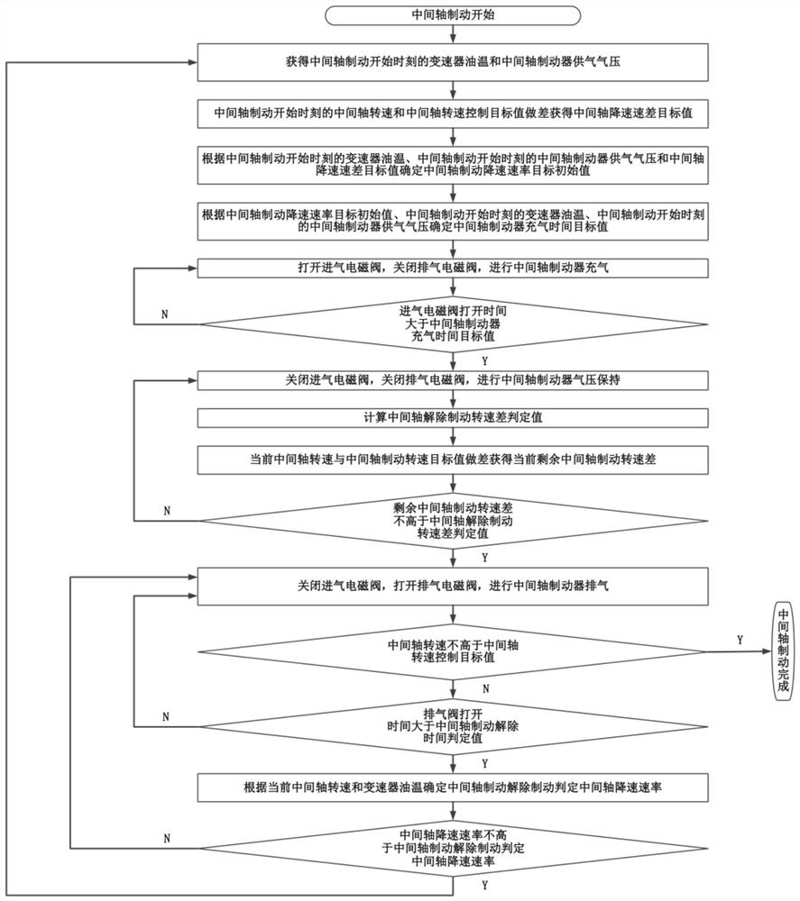
The invention relates to the technical field of automatic transmission control, and discloses an intermediate shaft brake control method. The intermediate shaft brake is inflated by opening the air inlet electromagnetic valve and closing the air exhaust electromagnetic valve, and the intermediate shaft braking capacity is established; after a period of time, the air inlet electromagnetic valve and the exhaust electromagnetic valve are closed, so that the air pressure of the intermediate shaft brake is kept, and the intermediate shaft is braked with stable braking torque; before the intermediate shaft rotating speed reaches the intermediate shaft rotating speed control target value, an exhaust electromagnetic valve is opened, intermediate shaft brake exhaust and intermediate shaft braking release are carried out, and if the intermediate shaft rotating speed does not reach the intermediate shaft rotating speed control target value and intermediate shaft braking release is carried out, the process is repeated; and until the intermediate shaft rotating speed reaches the intermediate shaft rotating speed control target value. Rapid speed reduction of the intermediate shaft is achieved, the rotating speed control precision of the intermediate shaft is improved, and it is guaranteed that when the rotating speed of the intermediate shaft reaches the target rotating speed of the intermediate shaft, intermediate shaft braking is relieved.

Description

technical field [0001] The invention relates to the technical field of automatic transmission control, in particular to a method for controlling an intermediate shaft brake. Background technique [0002] The sliding gear shifting method is widely used in automatic transmissions. During the upshifting process of the automatic transmission adopting the sliding gear shifting method, the speed of the intermediate shaft is reduced so that the sliding gear gear can complete the shifting action under a suitable speed difference. When the shift speed difference is inappropriate, the shifting of the sliding gear sleeve will cause problems such as large shifting impact, shift failure or even damage to the sliding gear sleeve. In order to shorten the shifting time and quickly complete the deceleration of the intermediate shaft, the intermediate shaft brake with the wet friction plate as the braking element and the cylinder as the actuator is widely used in the automatic transmission th...

Claims


Application Information

Patent Timeline
IPC IPC(8): F16D65/14F16D121/02
CPCF16D65/14F16D2121/02
Inventor 于跃李健华贾玉哲柳英杰张书郡费钟鸣谷守功高志飞孙国晖王巍巍
Owner FAW JIEFANG AUTOMOTIVE CO
Learn More