
Natural gas hydrate exploitation system and method combined with CO2 gas burying

A natural gas and hydrate technology, which is applied in the fields of mining fluids, other gas emission reduction technologies, earthwork drilling and production, etc., can solve the problems of reducing the risk of natural gas hydrate mining, causing geological disasters, and decreasing formation strength, so as to compensate for the loss of formation pressure , reduce stratum collapse, and achieve the effect of burying

Pending Publication Date: 2022-04-22
CHINA UNIV OF PETROLEUM (EAST CHINA) +1
View PDF0 Cites 0 Cited by
  • Summary
  • Abstract
  • Description
  • Claims
  • Application Information

AI Technical Summary

Problems solved by technology

[0005] The invention aims to solve the problem that the formation strength decline caused by the decomposition of natural gas hydrate in the process of natural gas hydrate exploitation is easy to cause geological disasters, and proposes a combined CO 2 Gas hydrate recovery system and method for gas storage, CO 2 Gas storage treatment is combined with natural gas hydrate exploitation, and carbon dioxide hydrate is formed by carbon dioxide burial to compensate for the decrease in formation strength caused by the decomposition of natural gas hydrate during exploitation. 2 At the same time, it reduces the risk of natural gas hydrate exploitation, laying the foundation for the commercial exploitation of natural gas hydrate

Method used


Image

  • Natural gas hydrate exploitation system and method combined with CO2 gas burying
  • Natural gas hydrate exploitation system and method combined with CO2 gas burying
  • Natural gas hydrate exploitation system and method combined with CO2 gas burying

Examples


Embodiment

[0044] This embodiment takes natural gas hydrate reservoirs in a certain sea area of ​​China as an example to illustrate a combined CO 2 The natural gas hydrate mining method for gas storage, specifically includes the following steps:

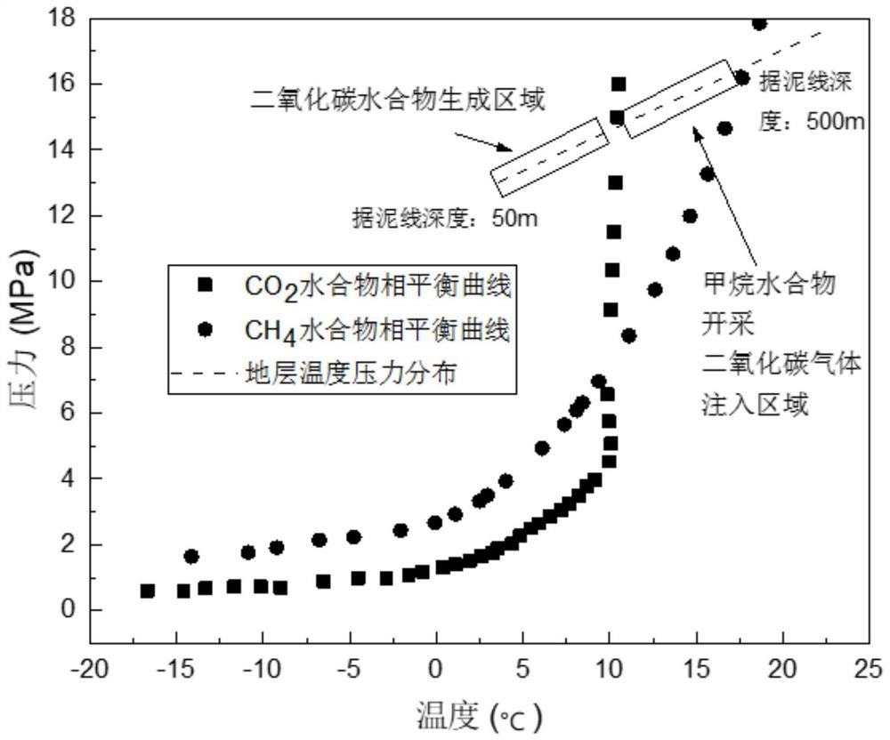
[0045] Step 1, according to the characteristics of gas hydrate reservoirs in this sea area determined by previous detection, such as figure 2 As shown, the figure includes the gas hydrate phase equilibrium curve, carbon dioxide hydrate phase equilibrium curve, formation temperature distribution characteristics and formation pressure distribution characteristics. The analysis shows that the gas hydrate formation and stable existence area is within 500m from the mud line. According to the According to the logging curve data in the sea area, the area with a distance of more than 315m from the mud line is classified as the underlying formation, the area with a distance of 205-315m from the mud line is classified as a natural gas hydrate reservoir,...


PUM


Abstract

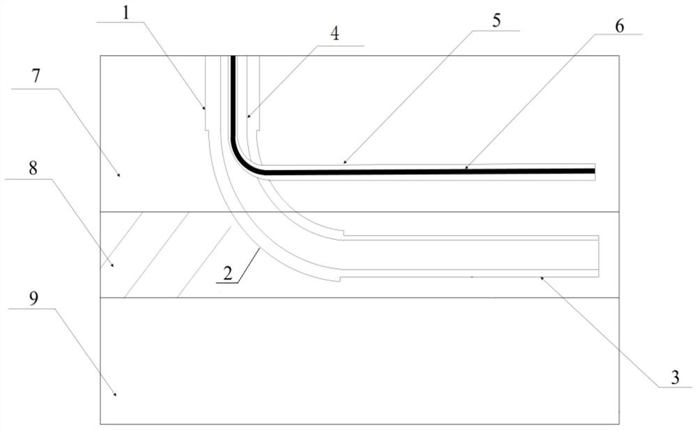
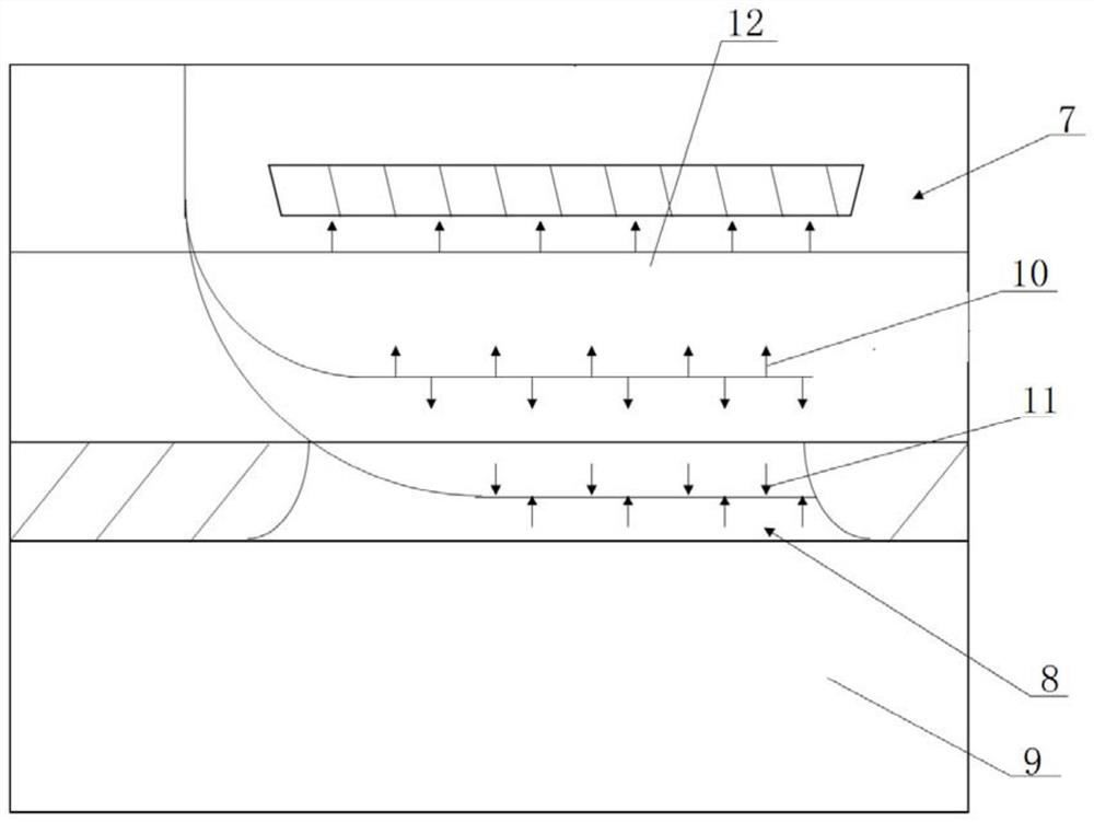
The invention discloses a CO2 gas burying combined natural gas hydrate exploitation system which comprises a drilling and exploitation platform, a production well and a CO2 gas injection well, the production well is sequentially provided with a vertical section, a transition section and a horizontal section, the top end of the production well is connected with the drilling and exploitation platform, the bottom end of the production well is communicated with a natural gas hydrate reservoir, a sleeve is arranged in the production well, and the CO2 gas injection well is arranged in the sleeve. The production pipe embedded with the CO2 gas injection pipe is sleeved with the casing pipe, and the bottom end of the production pipe is located in a natural gas hydrate reservoir to form a natural gas migration channel; a drill hole is formed in the transition section of the production well, the CO2 gas injection pipe extends out of the drill hole and extends into the overlying stratum along the CO2 gas injection well, and a CO2 gas injection channel is formed. The invention further discloses a natural gas hydrate exploitation method combining CO2 gas burying, natural gas hydrate exploitation and CO2 burying are combined, the stratum strength of a natural gas hydrate reservoir is effectively improved, the exploitation risk of the natural gas hydrate is reduced, and a foundation is laid for commercial exploitation of the natural gas hydrate.

Description

technical field [0001] The invention relates to the technical field of natural gas hydrate exploitation, in particular to a combined CO 2 Gas hydrate recovery system and method for gas storage. Background technique [0002] With the increasing demand for fossil energy in the industrial society, finding alternative energy sources for traditional oil and gas has become the focus of attention in the current energy field. Natural gas hydrate, also known as combustible ice, is one of the clean energy sources with mining potential. It mainly occurs in deep-water shallow formations and permafrost zones. It has the characteristics of large reserves, wide distribution and high energy density, making the development of natural gas hydrate The design of the program has become the research focus of countries all over the world. In recent years, the United States, Japan, Canada and other developed countries have carried out relevant research on the test production of natural gas hydrat...

Claims


Application Information

Patent Timeline
IPC IPC(8): E21B43/01E21B43/16
CPCE21B43/01E21B43/164Y02P90/70
Inventor 李阳程远方史吉辉闫传梁薛明宇杨翰林
Owner CHINA UNIV OF PETROLEUM (EAST CHINA)
Learn More