Handle structure for portable electric vacuum chuck

A vacuum suction cup, portable technology, applied in the direction of conveyor objects, transportation and packaging, etc., can solve the problems of unfavorable electrode ventilation and heat dissipation, limited application range, and low dimensional accuracy of finished products, so as to avoid internal water accumulation and increase the application range , the effect of prolonging the service life

Pending Publication Date: 2022-04-22
范赵荣
View PDF0 Cites 0 Cited by
  • Summary
  • Abstract
  • Description
  • Claims
  • Application Information

AI Technical Summary

Problems solved by technology

At present, in addition to bare-handed grasping, the more commonly used grasping tools include manual vacuum suction cups and electric vacuum suction cups. The existing manual vacuum suction cups cannot continue to add negative pressure during construction, and there is a safety hazard of falling off due to negative pressure reduction during construction. However, the existing electric suction cups have the following defects: (1) construction with water cannot be carried out, and the application range is limited; (2) the negative pressure is pumped intermittently, and there is still a potential safety hazard of falling off due to a sudden decrease in the negative pressure during construction; (3) It is not easy to open a through hole for the center of gravity in the center of the handle, which is not conducive to the operation of multiple suction cups in series to operate large-area plates, and is not conducive to the ventilation and heat dissipation of the electrodes; It is difficult to install; (5) The airway valve parts are fixed at two points, which cannot form a surface-to-surface fitting connection, and cannot guarantee the compactness and stability of the connection surface of the airway system during dynamic construction

Method used


Image

  • Handle structure for portable electric vacuum chuck
  • Handle structure for portable electric vacuum chuck
  • Handle structure for portable electric vacuum chuck

Examples


Embodiment Construction

[0051] In order to clearly illustrate the technical features of this solution, the present invention will be described in detail below through specific implementation modes and in conjunction with the accompanying drawings. In the following description, many specific details are set forth in order to fully understand the application, but the application can also be implemented in other ways different from those described here, therefore, the protection scope of the application is not limited by the specific details disclosed below. EXAMPLE LIMITATIONS.

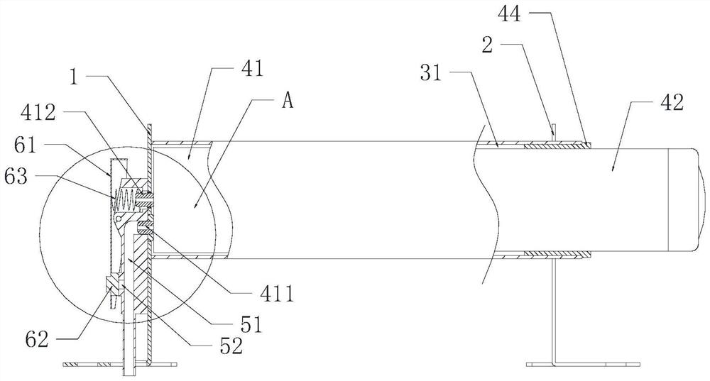
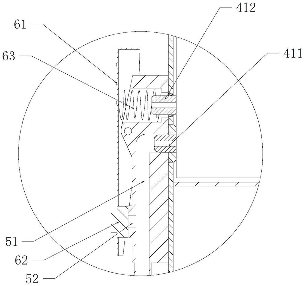
[0052] Such as Figure 1-6 As shown, in this embodiment, the handle structure for the portable electric vacuum chuck includes:

[0053] Front seat 1 and rear seat 2 for fixing with the main body of the suction cup;

[0054] The handle 3 erected on the front seat 1 and the rear seat 2, the handle 3 is formed with an installation channel 31, and the front seat 1 is provided with a panel to block the front end of the installati...


PUM


Abstract

According to the handle structure for the portable electric vacuum suction cup, the front base, the rear base, the handle, the air exhaust assembly, the air channel valve piece and the pressure relief switch are arranged in a matched mode, the structure of an existing electric suction cup is greatly simplified, and the handle structure for the portable electric vacuum suction cup has the advantages of being light, high in integration degree and convenient to operate, disassemble and assemble; through cooperative arrangement of the air passage valve piece and the pressing piece, air leakage and dustproof protection of the water and air pumping head can be achieved through one key, dust blown by air exhausted from the pressure relief opening cannot easily enter the micro vacuum pump from the water and air exhausting head, the service life of the micro vacuum pump is prolonged to a large extent, the failure rate is reduced, and the working efficiency is improved. Meanwhile, the problem that operation with water cannot be achieved on an existing electric suction cup is well solved, and the application range of the electric suction cup is widened.

Description

technical field [0001] The invention relates to the field of vacuum suction cups, in particular to a handle structure for a portable electric vacuum suction cup. Background technique [0002] During building construction or decoration, it is necessary to frequently grab building materials such as ceramic tiles, rock slabs, marble, astringent stone, steel plates, glass, templates, gypsum boards, and cement boards. At present, in addition to bare-handed grasping, the more commonly used grasping tools include manual vacuum suction cups and electric vacuum suction cups. The existing manual vacuum suction cups cannot continue to add negative pressure during construction, and there is a safety hazard of falling off due to negative pressure reduction during construction. However, the existing electric suction cups have the following defects: (1) construction with water cannot be carried out, and the application range is limited; (2) the negative pressure is pumped intermittently, a...

Claims


Application Information

Patent Timeline
IPC IPC(8): B65G47/91
CPCB65G47/91
Inventor 范赵荣范赵暄
Owner 范赵荣
Why Eureka
Try Eureka