Mechanical gripper with buffering function

A buffering and mechanical claw technology, applied in the field of mechanical claw, can solve the problems of inability to adjust the mechanical claw, damaged metal edges and corners, and reduce the practicability of the mechanical claw, so as to improve safety, prevent damage, and improve practicability and convenience. Effect

Inactive Publication Date: 2022-04-22
涟源市格宇石灰石矿业有限公司
View PDF0 Cites 0 Cited by
  • Summary
  • Abstract
  • Description
  • Claims
  • Application Information

AI Technical Summary

Problems solved by technology

[0002] The mechanical claw is an automatic operation device that can imitate certain movement functions of the human hand and arm to grab, carry objects or operate tools according to a fixed program. It is characterized by programming to complete various expected operations, structure and performance. Both human and mechanical claw machines have their own advantages. Mechanical claw is the earliest industrial robot and the earliest modern robot. It can replace human heavy labor to realize mechanization and automation of production, and can operate in harmful environments to protect Personal safety, so it is widely used in machinery manufacturing, metallurgy, electronics, light industry and atomic energy and other departments. The mechanical claws currently used will cause damage to the edges and corners of the metal due to the strong force of the mechanical claws when grasping metal, and affect the use of items at the same time. , reduce the practicability of the mechanical claws, most of the mechanical claws have low flexibility when used, and cannot adjust the angle of the mechanical claws themselves and the whole, which requires human intervention in the mechanical claws to grab objects, which increases the production cost. At the same time, the mechanical claws cannot grasp items of different heights, which reduces the practicability of the device

Method used


Image

  • Mechanical gripper with buffering function
  • Mechanical gripper with buffering function

Examples


Embodiment Construction

[0016] The following will clearly and completely describe the technical solutions in the embodiments of the present invention with reference to the accompanying drawings in the embodiments of the present invention. Obviously, the described embodiments are only some, not all, embodiments of the present invention. Based on the embodiments of the present invention, all other embodiments obtained by persons of ordinary skill in the art without making creative efforts belong to the protection scope of the present invention.

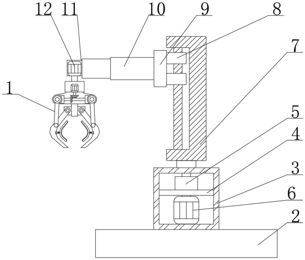
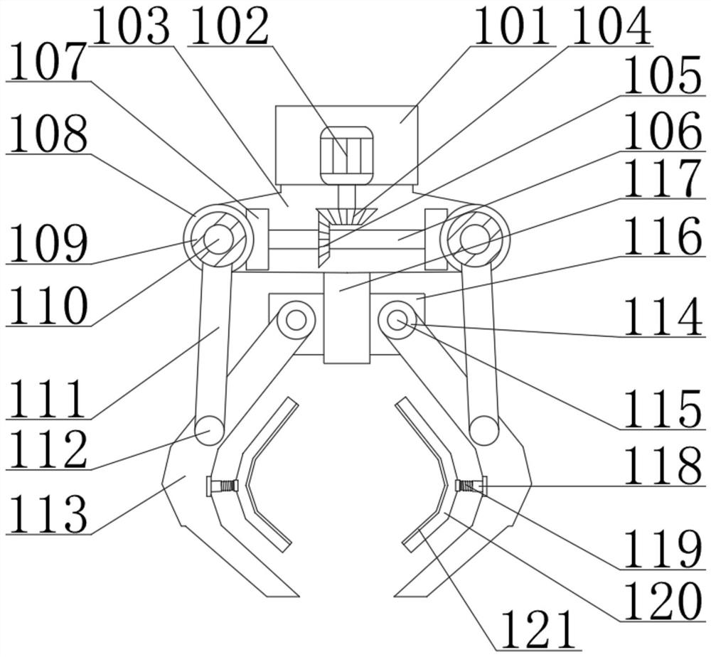
[0017] see Figure 1-2 , the present invention provides a technical solution:

[0018] A mechanical claw with a buffering effect, comprising a base 2, a linear motor 7 and a mechanical claw device 1, a motor box 3 is fixedly connected above the base 2, a first motor 6 is fixedly connected below the inside of the motor box 3, and the top of the inside of the motor box 3 A support plate 4 is fixedly connected, a reducer 5 is fixedly connected above the support ...


PUM


Abstract

The invention relates to the technical field of mechanical claws, in particular to a mechanical claw with a buffering function, which comprises a base, a linear motor and a mechanical claw device, a motor box is fixedly connected above the base, a first motor is fixedly connected below the interior of the motor box, and a support plate is fixedly connected above the interior of the motor box; a speed reducer is fixedly connected to the upper portion of the supporting plate, a linear motor is fixedly connected to a main shaft of the speed reducer, a sliding sleeve is slidably connected to a main shaft of the linear motor, a connecting block is fixedly connected to the left side of the sliding sleeve, a hydraulic cylinder is fixedly connected to the left side of the connecting block, and a connecting box is fixedly connected to the left end of the hydraulic cylinder. And a second motor is fixedly connected to the interior of the connecting box, a main shaft of the second motor is fixedly connected with a mechanical claw device, the height and direction of the mechanical claw device can be conveniently adjusted through the first motor, the second motor and a linear motor, the flexibility of the device is improved, and the mechanical claw device can conveniently grab different positions.

Description

technical field [0001] The invention relates to the technical field of mechanical claws, in particular to a mechanical claw with a buffering effect. Background technique [0002] The mechanical claw is an automatic operation device that can imitate certain movement functions of the human hand and arm to grab, carry objects or operate tools according to a fixed program. It is characterized by programming to complete various expected operations, structure and performance. Both human and mechanical claw machines have their own advantages. Mechanical claw is the earliest industrial robot and the earliest modern robot. It can replace human heavy labor to realize mechanization and automation of production, and can operate in harmful environments to protect Personal safety, so it is widely used in machinery manufacturing, metallurgy, electronics, light industry and atomic energy and other departments. The mechanical claws currently used will cause damage to the edges and corners of...

Claims


Application Information

Patent Timeline
IPC IPC(8): B25J9/12B25J15/02B25J15/08
CPCB25J9/123B25J9/126B25J15/0206B25J15/0213B25J15/08
Inventor 喻伟雁
Owner 涟源市格宇石灰石矿业有限公司
Why Eureka
Try Eureka