Receiving and launching barrel turnover device

A technology of sending and receiving bulbs and turning devices, which is applied in drilling equipment, wellbore/well components, earth-moving drilling and mining, etc., can solve the problems of large risks, inconvenient transportation, and inability to fix steadily, so as to reduce the impact and improve the practicability. and convenience

Pending Publication Date: 2022-04-05
SHENZHEN OFFSHORE OIL ENG UNDERWATER TECH
View PDF0 Cites 1 Cited by
  • Summary
  • Abstract
  • Description
  • Claims
  • Application Information

AI Technical Summary

Problems solved by technology

The receiving and receiving barrel needs to be switched between horizontal and vertical states many times during offshore construction. However, due to the shape of the receiving and receiving barrel itself, it is still difficult and inconvenient to perform this operation only on the receiving and receiving barrel itself.
[0004] In addition, due to the shape of the horizontal receiving and receiving tube, it cannot be fixed on the plane smoothly, and there is a greater risk during sea transportation; and one end of the receiving and receiving tube needs to be connected with the underwater connector, and there is no Greater wear
In short, the main problems for the receiving and receiving ball are mainly the difficulty of turning over, the inconvenience of transportation, etc.

Method used


Image

  • Receiving and launching barrel turnover device
  • Receiving and launching barrel turnover device
  • Receiving and launching barrel turnover device

Examples


Embodiment Construction

[0028] In order to have a clearer understanding of the technical features, purposes and effects of the present invention, the specific implementation manners of the present invention will now be described in detail with reference to the accompanying drawings.

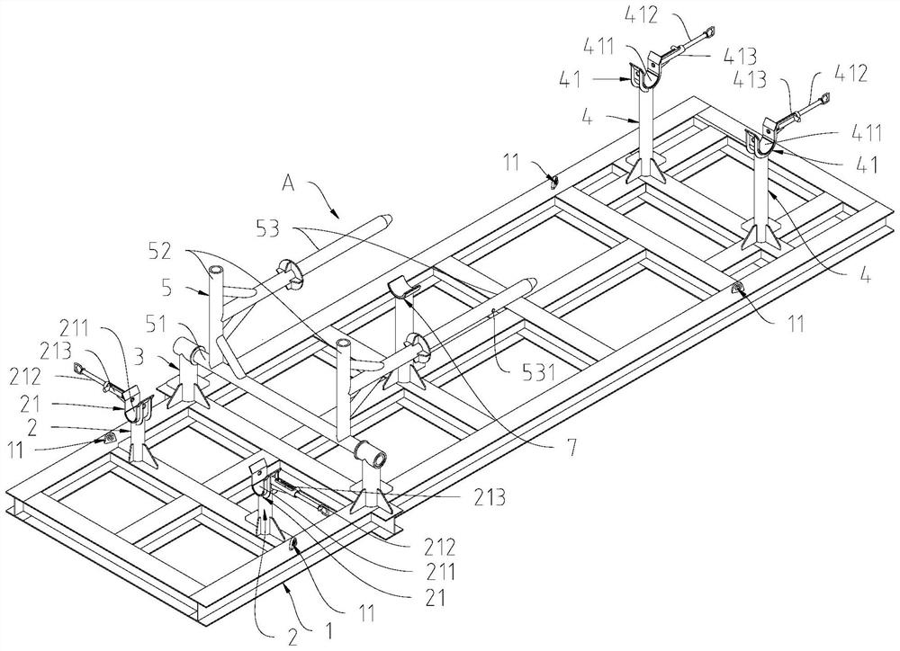
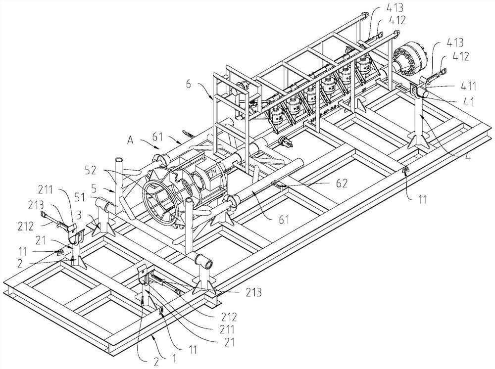
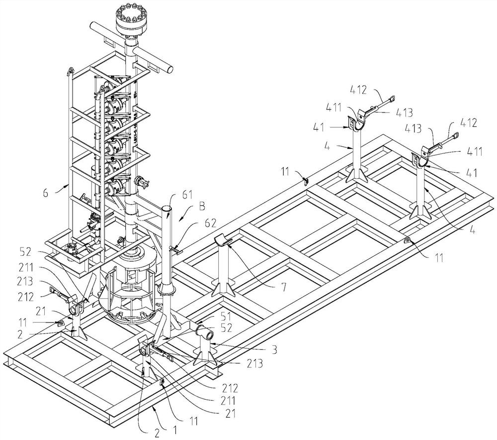
[0029] Such as Figure 1 to Figure 3 As shown, the receiving and receiving ball tube turning device in a preferred embodiment of the present invention includes a base 1 , a front support base 2 , a middle support base 3 , a rear support base 4 , and an overturn frame 5 .

[0030] The front support seat 2, the middle support seat 3, and the rear support seat 4 are arranged at intervals successively on the base 1, so that the receiving and receiving ball tube 6 can be supported when it is placed horizontally or erected.

[0031] The overturn frame 5 can rotate between the first rotation position A and the second rotation position B. The overturn frame 5 includes an overturn seat 51 that is rotatably engaged with the middl...


PUM


Abstract

The invention relates to a ball receiving and sending cylinder turnover device which comprises a base, a front supporting seat, a middle supporting seat, a rear supporting seat and a turnover frame. The front supporting seat, the middle supporting seat and the rear supporting seat are sequentially arranged on the base at intervals; the overturning frame can rotate between a first rotating position and a second rotating position, the overturning frame comprises an overturning seat in rotating fit with the middle supporting seat, a supporting part extending from the overturning seat in the side direction and at least two guide columns, an included angle is formed between the supporting part and the guide columns, and the guide columns are used for being connected with sleeves of the ball receiving and sending barrels in a sleeving mode so as to be connected with the ball receiving and sending barrels; when the overturning frame is at the first rotating position, the guide column is arranged in the horizontal direction and extends out of the rear supporting seat, so that the ball receiving and sending barrel can be supported on the rear supporting seat, and the supporting part faces upwards; and when the overturning frame is located at the second rotating position, the guide column is arranged upwards, so that the receiving and dispatching air cylinder can be erected, and the supporting part is horizontally arranged and supported to the front supporting seat. The ball receiving and sending cylinder turnover device enables the ball receiving and sending cylinders to be turned over, transported, tested and stored underwater, and is practical and convenient.

Description

technical field [0001] The invention relates to the field of offshore oil engineering, and more specifically relates to a flipping device for a receiving and receiving ball cylinder. Background technique [0002] With the continuous development of offshore oil, major offshore oil companies are increasing the development of deep water oil fields. Deepwater pre-commissioning is an inspection of the installation quality of underwater facilities, and it is also an important link before underwater pipelines are put into production. During the construction process of submarine pipeline pre-commissioning, it is necessary to use the receiving and receiving ball to carry out pipeline pigging, diameter measurement and other work. [0003] During the underwater use, the receiving and receiving tube usually needs to be connected in a vertical state. Due to the higher height in the vertical state, there is a greater risk. When carrying out operations such as transportation, testing, an...

Claims


Application Information

Patent Timeline
IPC IPC(8): E21B19/14E21B41/00
Inventor 高磊李怀亮崔宁陈娟曹聚杭蒋兵兵杨盛宋建堂张捷马国强
Owner SHENZHEN OFFSHORE OIL ENG UNDERWATER TECH
Why Eureka
Try Eureka