
Annular electromagnetic induction pump

An electromagnetic induction and electromagnetic pump technology, applied in the field of electromagnetic pumps, can solve the problems of assembling the electromagnetic pump system, such as difficult, difficult to adjust, and non-adjustable, to achieve the effects of increasing usability, ensuring heat transfer, and improving reliability

Pending Publication Date: 2022-04-19
原子能和辅助替代能源委员会
View PDF0 Cites 0 Cited by
  • Summary
  • Abstract
  • Description
  • Claims
  • Application Information

AI Technical Summary

Problems solved by technology

However, the force provided by the internal spring is not adjustable unless the internal sensor is removed and the contact system is changed
[0023] In all these solutions offered, the system for assembling the electromagnetic pump is difficult, and the contact induction system is long and difficult to adjust, or even impossible to adjust in the case of internal induction

Method used


Image

  • Annular electromagnetic induction pump
  • Annular electromagnetic induction pump
  • Annular electromagnetic induction pump

Examples


Embodiment Construction

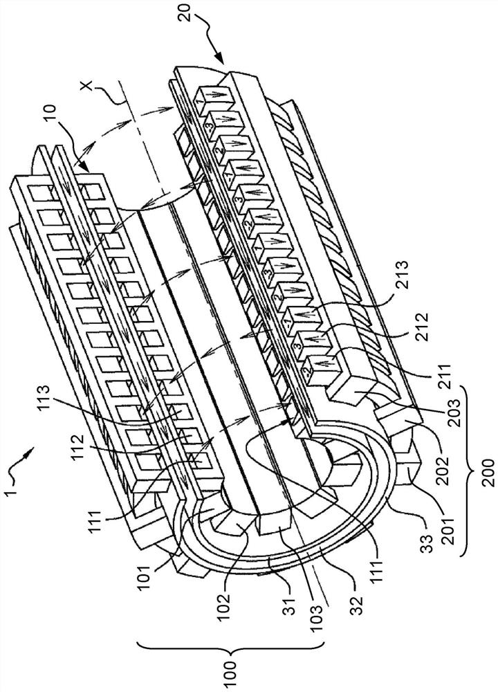
[0065] Describe the prior art ring electromagnetic induction pump's figure 1 It has been described above and will not be reconsidered here.

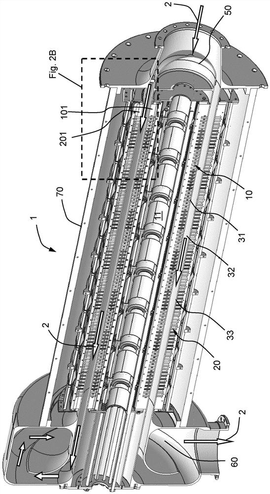
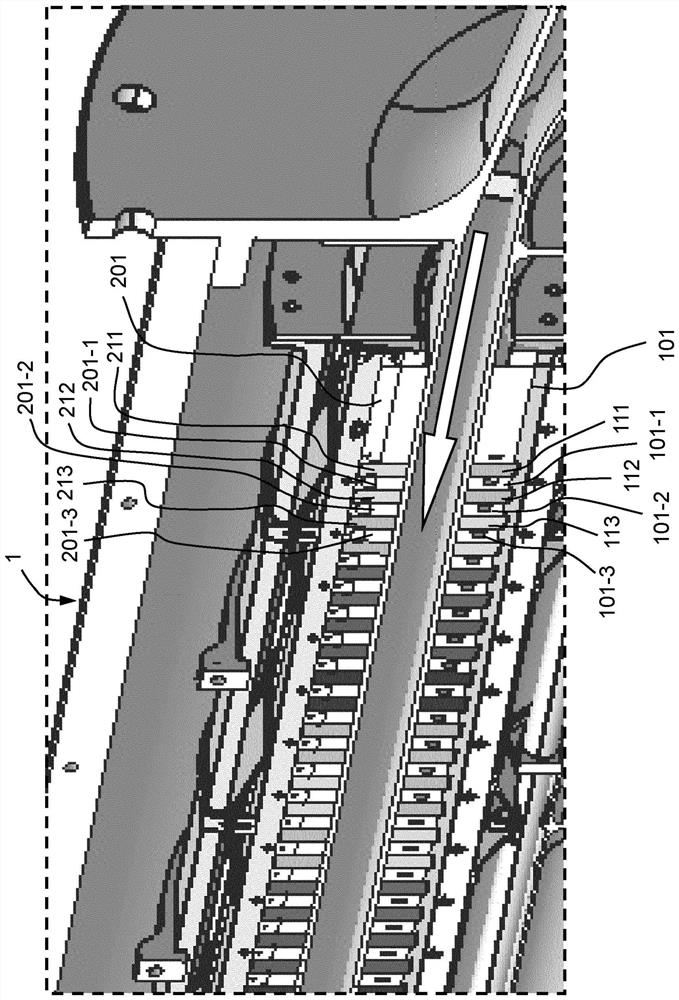
[0066] Figure 2A , 2B , 3A and 3B depict an embodiment of an electromagnetic pump according to the invention, and Figure 3A and 3B Specifically depicting the pump's internal sensor. Figure 4 The moving device of the electromagnetic pump according to the embodiment is described in detail. Figure 5A and 5B The mobile device is depicted in two different radial positions.

[0067] The electromagnetic pump is a ring electromagnetic induction pump, which is figure 1 In the same way the electromagnetic pump of the shown prior art starts from the central axis X of the electromagnetic pump 1 (which is also the longitudinal direction) comprising:

[0068] - internal inductor (or internal stator) 10;

[0069] - the inner tube 31, which contains the inner inductor;

[0070] - a pumping channel 32 in which the fluid 2 to be pumped can c...


PUM


Abstract

The invention relates to an electromagnetic induction pump comprising:-a tubular inner inductor comprising a plurality of inner combs and inner coils positioned between the teeth of said inner combs, the interior of said inner inductor forming a cavity; an inner tube positioned around the inner inductor; -a pumping channel allowing circulation of the fluid to be pumped,-an outer tube, the channel being located between the inner tube and the outer tube; -a tubular outer inductor positioned around the outer tube and comprising a plurality of outer combs and outer coils positioned between the teeth of said outer combs; the electromagnetic pump further comprises moving means for moving the inner comb part and capable of changing the radial gap between said inner comb part and the inner tube and comprising a first part positioned inside the inner inductor and connected to the inner comb part so as to enable radial movement of the inner comb part. And a second portion extending at least partially outside the internal inductor and connected to the first portion in a manner to control the first portion.

Description

technical field [0001] The present invention relates to electromagnetic pumps (which may hereinafter be referred to as "EM pumps"), and more particularly to ring EM induction pumps, especially those high power electromagnetic pumps typically above 500 kW. [0002] The invention can find application notably in sodium cooled fast neutron reactors (commonly referred to as "Na FNR"), especially in the secondary cooling loop of a NaFNR. Background technique [0003] Generally, it is known practice to use electromagnetic pumps to pump liquid metals. In certain areas of use with liquid metals, such pumps actually offer advantages over mechanical pumps. Solenoid pumps do not require a lubrication circuit as they have no moving parts and therefore no parts that need to be lubricated. This provides greater reliability compared to mechanical pumps. Furthermore, the cooling circuit for the electromagnetic pump advantageously uses the liquid metal it is pumping, such as sodium. In th...

Claims


Application Information

Patent Timeline
Patent Type & Authority Applications(China)
IPC IPC(8): H02K44/06
CPCH02K44/06Y02E30/30G21C15/247H02K44/02
Inventor F·雷伊
Owner 原子能和辅助替代能源委员会
Learn More