
Returning light monitoring device of pulse fiber laser

A fiber laser and monitoring device technology, applied in the laser field, can solve problems such as real-time monitoring during the application process, and achieve the effects of online real-time monitoring of return light power, low cost, and high integration

Pending Publication Date: 2022-04-19
SHANGHAI FEIBO LASER TECH CO LTD
View PDF5 Cites 0 Cited by
  • Summary
  • Abstract
  • Description
  • Claims
  • Application Information

AI Technical Summary

Problems solved by technology

Different from continuous light, for pulsed light, first, the signal optical power of the pulse varies with parameters (different pulse widths and frequencies correspond to different signal optical powers, and even customers will directly modulate the power), and there are countless combinations of parameters that customers may use. First, it is impossible to calibrate the power one by one before application, and it can only be monitored in real time during the application process; second, to monitor the signal optical power in the application, it is necessary to strictly distinguish the return light and signal light in order to accurately calibrate the signal optical power. Inversely deriving the return optical power

Method used


Image

  • Returning light monitoring device of pulse fiber laser
  • Returning light monitoring device of pulse fiber laser
  • Returning light monitoring device of pulse fiber laser

Examples


Embodiment Construction

[0027] The following is attached figure 1 to attach Figure 6 The present invention is described in further detail.

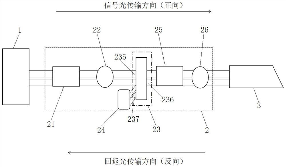
[0028] The embodiment of the invention discloses a pulsed fiber laser return light monitoring device. The present invention can separate return light and signal light, accurately calibrate signal light, and monitor the power of return light in real time online. Its main functional structure is as attached figure 1 shown in the dotted box. attached figure 1 The uppermost arrow in the figure is the signal light transmission direction (forward direction), and the lowermost arrow is the return light transmission direction (reverse direction).

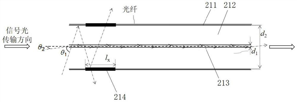
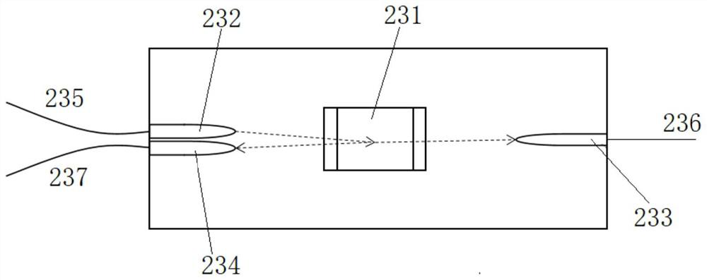
[0029] The return light monitoring device 2 is located between the laser gain fiber 1 and the laser output head 3, including a forward cladding optical processor 21, a forward core optical detector 22, a reverse core optical processor 23, a reverse core Light collector 24 , reverse cladding light processor 25 , and ligh...


PUM

PropertyMeasurementUnit
isolationaaaaaaaaaa

Abstract

The invention relates to a pulse fiber laser return light monitoring device, which belongs to the technical field of laser, is connected between a laser gain fiber and a laser output head, and comprises a forward cladding optical processor, a forward fiber core optical detector, a reverse fiber core optical processor, a reverse cladding optical processor and an optical detector which are connected in sequence, and the laser gain optical fiber and the laser output head are respectively connected with the forward cladding optical processor and the optical detector. Returning light and signal light can be separated, the signal light can be accurately calibrated, and the power of the returning light can be monitored on line in real time.

Description

technical field [0001] The invention belongs to the field of laser technology, and relates to a fiber laser, in particular to a pulse fiber laser return light monitoring device. Background technique [0002] Pulsed fiber lasers are widely used in the industrial field. When processing highly reflective materials, the laser reflected from the surface of the material will be coupled into the laser through the output head of the laser and act on the core components inside the laser, resulting in unstable operation of the laser. It may even cause permanent damage to the laser. In order to meet more complex application scenarios, real-time monitoring and feedback of the returned light is beneficial to protect the laser and guide the specific operation of the customer's application end, avoiding the laser from being affected by the returned light. [0003] In continuous fiber lasers, the power difference method is generally used to monitor the return light. The specific method is:...

Claims


Application Information

Patent Timeline
Patent Type & Authority Applications(China)
IPC IPC(8): H01S3/00
CPCH01S3/0014
Inventor 谭小妹刘赟李文涛李骁军
Owner SHANGHAI FEIBO LASER TECH CO LTD
Learn More