
Intelligent charging pile based on photovoltaic power generation

A technology of intelligent charging and photovoltaic power generation, which is applied in photovoltaic power generation, electric vehicle charging technology, support structure of photovoltaic modules, etc., which can solve the problem of poor stability and flexibility of photovoltaic energy absorption, reduction of solar energy absorption efficiency, and lack of buffering of charging piles. performance and other issues, to achieve the effect of increasing multiple buffering performance, improving stability and flexibility, and solving up and down adjustability

Active Publication Date: 2022-04-15
日照宇通坤和电力科技有限公司 +2
View PDF7 Cites 0 Cited by
  • Summary
  • Abstract
  • Description
  • Claims
  • Application Information

AI Technical Summary

Problems solved by technology

[0003] Existing smart charging piles have the following deficiencies: 1. The sun will move, and the photovoltaic panels of existing charging piles are mostly fixed structures, which cannot follow the sun's direction, which greatly reduces the efficiency of the sun's energy absorption. and poor flexibility; 2. When the existing charging piles are used, when the car is close to the charging piles, it is easy to hit the charging piles, and the charging piles are easily damaged by impact, which reduces the protection of the charging piles. 3. The charging positions of the existing charging piles are mostly fixed structures, and the charging height cannot be adjusted, which reduces the scope of application of the charging piles. Therefore, we propose a new type of charging pile based on photovoltaic power generation. Smart charging pile

Method used


Image

  • Intelligent charging pile based on photovoltaic power generation
  • Intelligent charging pile based on photovoltaic power generation
  • Intelligent charging pile based on photovoltaic power generation

Examples


Embodiment

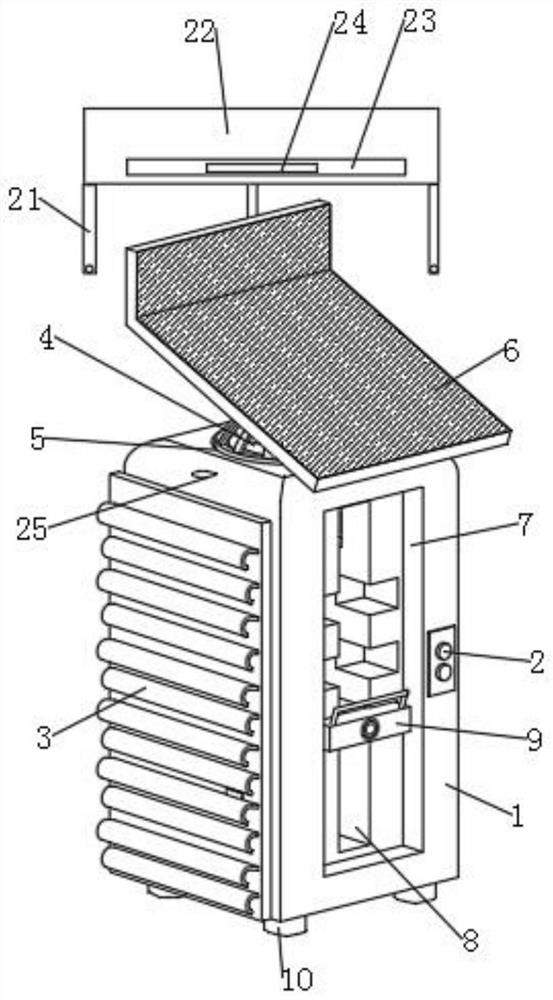
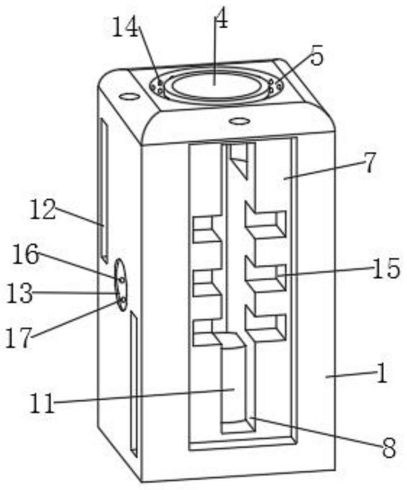
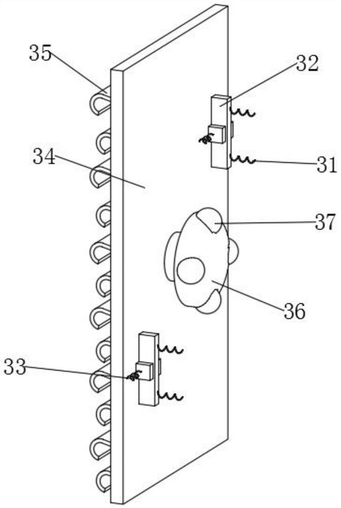
[0047] Such as Figure 1-Figure 7 As shown, a smart charging pile based on photovoltaic power generation includes a charging pile main body 1, a switch button 2 is provided at the rear of the right end of the charging pile main body 1, and a protective structure 3 is fixedly connected to the front end of the charging pile main body 1, The upper end of the charging pile main body 1 is provided with a steering slot 4 and a rotating slot 5, and the charging pile main body 1 is jointly provided with a photovoltaic structure 6 through the steering slot 4 and the rotating slot 5, and the upper end of the charging pile main body 1 is opened all around. There are threaded holes 25, the main body of the charging pile 1 is provided with a rain-proof structure 21 through the threaded holes 25, the left end and the right end of the main body of the charging pile 1 are provided with adjustment grooves 7, and the inside of the main body 1 of the charging pile is provided with a device slot ...


PUM


Abstract

The intelligent charging pile comprises a charging pile body, a switch button is arranged on the rear portion of the right end of the charging pile body, a protection structure is fixedly connected to the front end of the charging pile body, and a steering groove and a rotating groove are formed in the upper end of the charging pile body; the charging pile body is jointly provided with a photovoltaic structure through a steering groove and a rotating groove, adjusting grooves are formed in the left end and the right end of the charging pile body correspondingly, a device groove is formed in the charging pile body and communicates with the two adjusting grooves, and charging structures are arranged in the two adjusting grooves correspondingly. The lower end of the charging pile body is fixedly connected with a set of supporting legs, and each set of supporting legs comprises four supporting legs which are symmetrically distributed in pairs. According to the invention, the characteristic of real-time follow-up energy absorption angle of sun movement is realized, the buffering performance and the protection area of the charging pile in collision are improved, the charging height is adjustable, and the charging pile is convenient for a user to use.

Description

technical field [0001] The invention relates to the technical field of photovoltaic power generation charging piles, in particular to an intelligent charging pile based on photovoltaic power generation. Background technique [0002] Photovoltaic power generation is a technology that directly converts light energy into electrical energy by using the photovoltaic effect of the semiconductor interface. Most of the current environmental protection equipment uses photovoltaic power generation technology, especially the charging pile for intelligent charging of the car body. [0003] Existing smart charging piles have the following deficiencies: 1. The sun will move, and the photovoltaic panels of existing charging piles are mostly fixed structures, which cannot follow the sun's direction, which greatly reduces the efficiency of the sun's energy absorption. and poor flexibility; 2. When the existing charging piles are used, when the car is close to the charging piles, it is easy t...

Claims


Application Information

Patent Timeline
Patent Type & Authority Applications(China)
IPC IPC(8): B60L53/51B60L53/31H02S20/32B60L53/30
CPCB60L53/51B60L53/31H02S20/32B60L53/30Y02T90/12
Inventor 刘贤君晋登泽吕晓东陈海燕刘红梅高俊杰薛翔天王飞吕鹏峰薛程
Owner 日照宇通坤和电力科技有限公司
Learn More