
Flying saucer type no-net filtering slag pressing machine

A technology of meshless filtration and slag press, which is used in filtration and separation, mobile filter element filters, separation methods, etc., can solve the problems of small particle diameter requirements and high water content of sediment, and achieve low operating costs and water in slag output. The effect of low rate and less wearing parts

Pending Publication Date: 2022-04-15
沈智奇
View PDF0 Cites 0 Cited by
  • Summary
  • Abstract
  • Description
  • Claims
  • Application Information

AI Technical Summary

Problems solved by technology

[0006] In view of the above-mentioned technical problems, the object of the present invention is to provide a flying saucer type meshless filter slag press machine, which solves the problem of high moisture content of the sediment discharged during the operation of the above-mentioned disc centrifuge, and when the sediment accumulation in the inner cavity of the drum and the surface of the disc is too thick. The whole drum needs to be disassembled and cleaned manually and the particle diameter requirement in the treatment liquid is very small.

Method used


Image

  • Flying saucer type no-net filtering slag pressing machine
  • Flying saucer type no-net filtering slag pressing machine
  • Flying saucer type no-net filtering slag pressing machine

Examples


Embodiment Construction

[0038] Below in conjunction with the accompanying drawings, the embodiments of the flying saucer type meshless filter slag press of the present invention are described in detail:

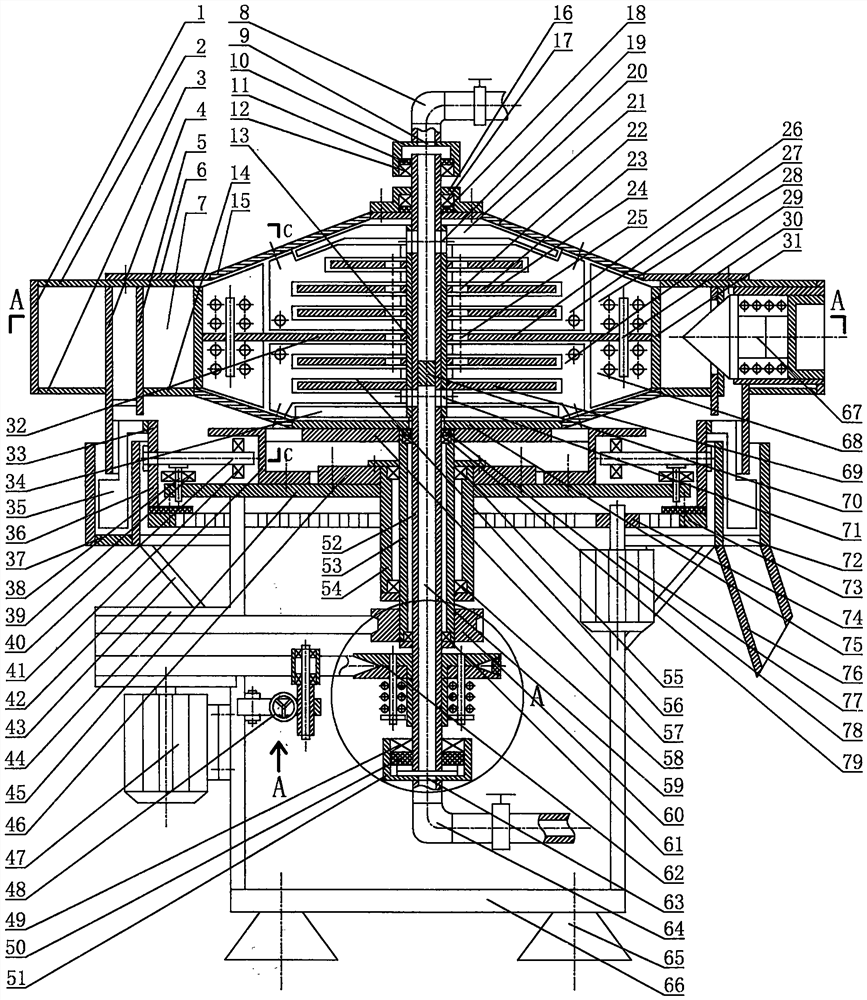
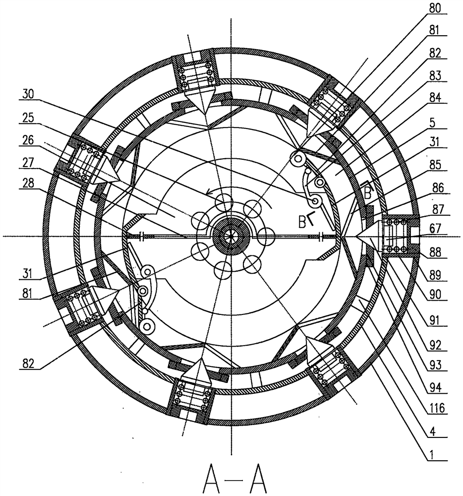
[0039] The flying saucer type meshless filter slag press of the present invention is composed of a frame 66, a drive motor 47, a high-speed differential device 59, a flying saucer-type drum 21, a solid-liquid separation system 32, a slag scraping device, a slag discharge system, a deceleration motor 76, The slag discharge system 33, the water inlet and the water outlet are constituted: the frame 66 is provided with a drive motor 47, and the base plate 45 at the upper end of the frame 66 is provided with a high-speed differential device 59, which is driven by the drive motor 47 to rotate at a differential speed Operation, a flying saucer-type rotating drum 21 is arranged above the high-speed differential device 59, and the rotating operation is driven by the high-speed differential device 59. The dru...


PUM


Abstract

The invention relates to a flying saucer type net-free filtering slag pressing machine which is composed of a rack, a driving motor, a high-speed differential device, a rotary drum assembly, a solid-liquid separation system, a differential motor, a slag discharging system, a water inlet pipe and a water outlet pipe. The driving motor is arranged on the rack to drive the high-speed differential device on a base plate of the rack to work, the flying saucer type rotary drum is arranged above the high-speed differential device and is driven by the high-speed differential device to work, the solid-liquid separation system is arranged in the rotary drum and is driven by the high-speed differential device to work, and the slag discharging system is arranged on the periphery of the rotary drum and is driven by a slag scraping driving disc to discharge slag. The slag discharging system is arranged below the slag discharging system and driven by a gear motor to discharge slag in a rotating mode, and a water inlet pipe and a water outlet pipe are arranged below and above the center shaft respectively; during operation, a to-be-treated liquid material is fed from the water inlet pipe and flows into the rotary drum through the center shaft, purified water separated at a high speed by the solid-liquid separation system flows into the center shaft from the center of the upper end in the rotary drum and flows out of the machine through the water outlet pipe, and highly-concentrated sediment separated at a high speed is discharged by the slag discharging system, falls into the slag discharging system and is discharged out of the machine.

Description

technical field [0001] The technology relates to a solid-liquid separation technology, which belongs to the field of solid-liquid separation and concentration. Background technique [0002] At present, the disc centrifugal separators on the market rely on the centrifugal force generated by the high-speed operation of the discs in the drum to separate the solid and liquid in the drum. The complex slag discharge device performs timed slag discharge, and this structural design has the following disadvantages: [0003] 1. The water content of the discharged sediment is as high as 95% or more, which cannot be recycled and used directly; [0004] 2. When the slag adhered to the surface of the discs in the inner cavity of the drum reaches a certain thickness, normal work cannot be performed, and the entire drum should be disassembled to remove the slag; [0005] 3. The particle diameter of the treated solid and liquid is 0.001-0.1 mm, which is too high for the diameter of the tre...

Claims


Application Information

Patent Timeline
IPC IPC(8): B01D33/21B01D33/46
Inventor 沈智奇
Owner 沈智奇
Learn More