
Novel single-Dewar high-efficiency motor structure

A motor structure, single Dewar technology, applied in the direction of magnetic circuit shape/style/structure, electromechanical devices, electrical components, etc., can solve the problems of large amount of liquid nitrogen consumption, long refrigeration time, high motor cost, etc., to reduce the amount of consumption, process Simple and cost-effective

Pending Publication Date: 2022-04-12
HARBIN ELECTRIC MASCH CO LTD
View PDF0 Cites 2 Cited by
  • Summary
  • Abstract
  • Description
  • Claims
  • Application Information

AI Technical Summary

Problems solved by technology

[0002] The motor is an electromagnetic device that converts or transmits electromechanical energy according to the law of electromagnetic induction. It is closely related to people's lives. With the continuous development of the motor industry, green energy has attracted more and more attention from the country, making large-capacity and high-efficiency motors more and more important. , but large-capacity motors are often affected by loss and heat, the volume often increases a lot, and the efficiency decreases. However, the windings in low-temperature environments have low resistance due to their low heat generation. Therefore, motors with this feature are important in the future. One of the development directions
[0003] However, due to the current low-temperature environment, the motor has a double-layer Dewar structure, and a vacuum layer is left between the Dewars, so that the overall volume of the motor is relatively large, and the air gap is usually more than 25mm, and the excitation coil and the iron core of the motor are placed in the liquid as a whole. Cooling in nitrogen makes the overall cooling power larger, the cooling time longer, and the amount of liquid nitrogen used is too large, resulting in the overall high cost of the motor. Therefore, it is urgent to develop a new single-Dewar high-efficiency motor structure

Method used


Image

  • Novel single-Dewar high-efficiency motor structure
  • Novel single-Dewar high-efficiency motor structure
  • Novel single-Dewar high-efficiency motor structure

Examples


Embodiment Construction

[0035] The present invention will be further described below in conjunction with the accompanying drawings and specific embodiments.

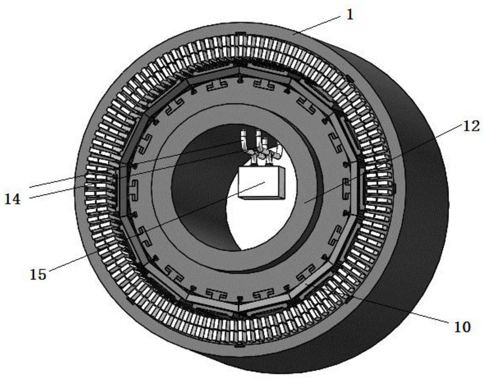
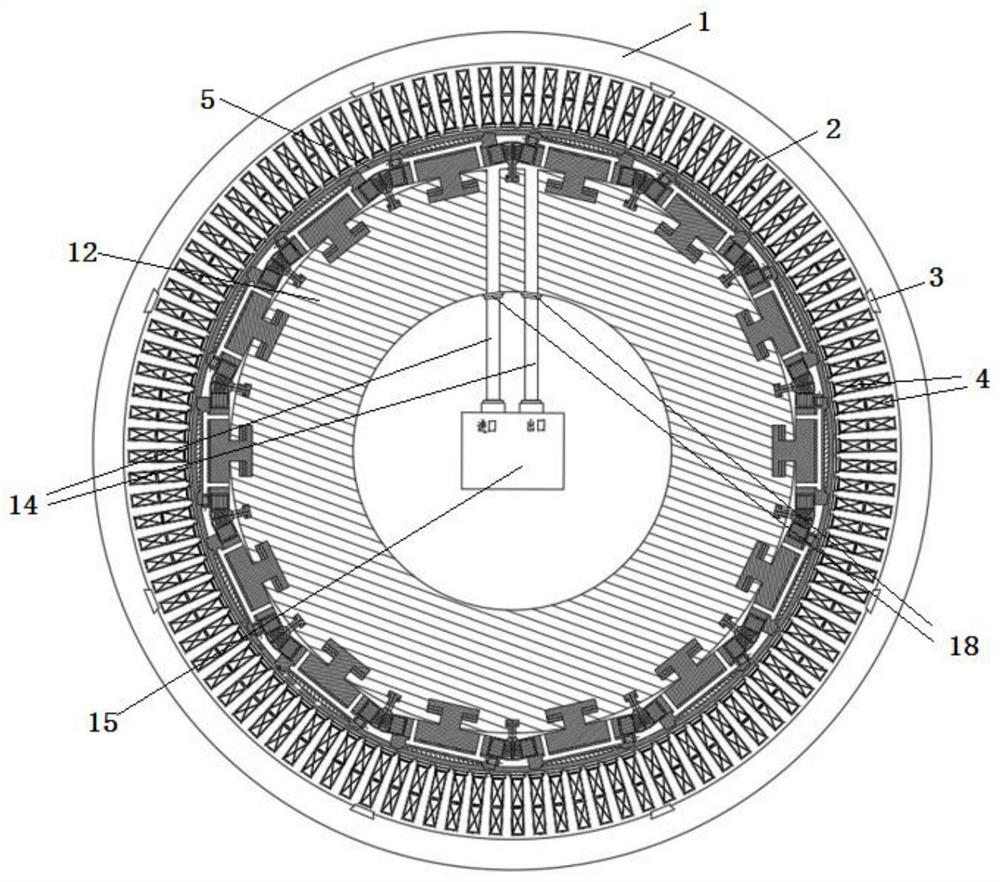
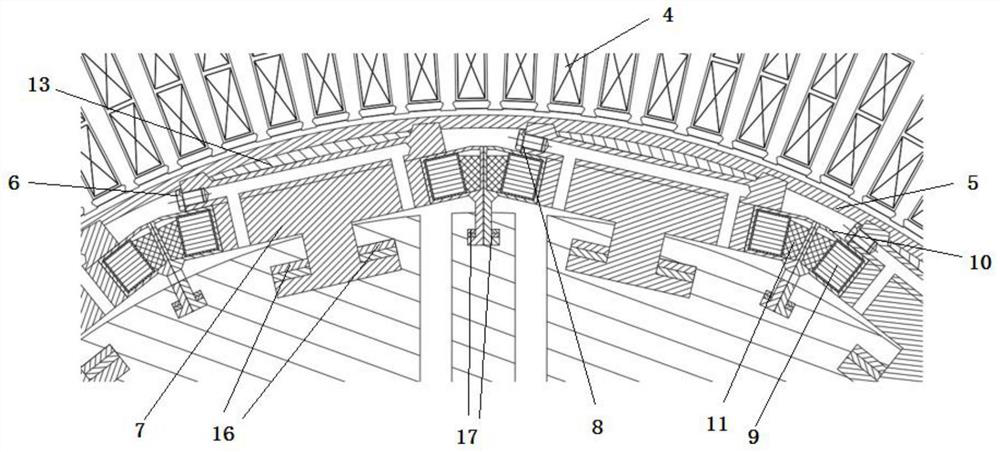
[0036] Such as figure 1 , 2 , 3, a new single Dewar high-efficiency motor structure consists of a stator yoke 1, a stator tooth 2, a dovetail key 3, a stator winding 4, a Dewar sleeve 5, a plug 6, a rotor core 7, a stopper Moving gasket 8, excitation coil 9, coil support 10, coil stopper 11, rotating shaft 12, copper shielding block 13, coolant circulation pipe 14, cooler 15, rotor core oblique key 16, coil support oblique key 17 , sealing ring 18; the stator yoke 1 is connected to the stator teeth 2 through the dovetail key 3, the stator windings 4 are respectively placed in the slots between the stator teeth 2, and the Dewar sleeve 5 is arranged on the stator teeth 2 Inside, there is a 5mm air gap between the Dewar sleeve 5 and the stator teeth 2. The rotor cores 7 are arranged inside the Dewar sleeve 5 and distributed along the circumferen...


PUM


Abstract

The invention discloses a novel single Dewar high-efficiency motor structure which is composed of a stator yoke part, a stator tooth part, a dovetail key, a stator winding, a Dewar sleeve, a screwed plug, a rotor iron core, a locking gasket, a magnet exciting coil, a coil supporting piece, a coil stop block, a rotating shaft, a copper shielding block, a cooling liquid circulation pipeline, a cooler, a rotor iron core taper key, a coil supporting piece taper key and a sealing ring. According to the invention, the operation efficiency of the motor is improved, more stator windings are placed in the stator slots, the stator volume is reduced, the vacuum volume is effectively reduced, heat transfer from the stator to the rotor direction is isolated, and the assembly and later maintenance are convenient. The capacity of the required cooling liquid and the power of the cooler are effectively reduced. The whole structure is simple, the rotor core and the coil supporting piece are both of an independent structure, the rotor core and the coil supporting piece can be installed only by vertically placing the bottom feet of the rotor core and the coil supporting piece in the T-shaped grooves of the rotating shaft, and installation is convenient.

Description

technical field [0001] The invention relates to the field of generators, in particular to a novel single Dewar high-efficiency motor structure. Background technique [0002] The motor is an electromagnetic device that converts or transmits electromechanical energy according to the law of electromagnetic induction. It is closely related to people's lives. With the continuous development of the motor industry, green energy has attracted more and more attention from the country, making large-capacity and high-efficiency motors more and more important. , but large-capacity motors are often affected by loss and heat, the volume often increases a lot, and the efficiency decreases. However, the windings in low-temperature environments have low resistance due to their low heat generation. Therefore, motors with this feature are important in the future. One of the directions of development. [0003] However, due to the current low-temperature environment, the motor has a double-laye...

Claims


Application Information

Patent Timeline
Patent Type & Authority Applications(China)
IPC IPC(8): H02K1/14H02K1/22H02K3/46H02K1/32H02K9/19
Inventor 朱一枫张艳竹苟智德张春莉胡刚李桂芬谢雨
Owner HARBIN ELECTRIC MASCH CO LTD
Learn More