Self-heating battery thermal management control device, battery assembly, electric vehicle and method

A battery thermal management and control device technology, which is applied in the direction of secondary batteries, circuits, electrical components, etc., can solve problems such as the inability to realize efficient cooling of power batteries, automatic heating of battery packs, etc.

Pending Publication Date: 2022-04-12
CHINA FIRST AUTOMOBILE
View PDF3 Cites 1 Cited by
  • Summary
  • Abstract
  • Description
  • Claims
  • Application Information

AI Technical Summary

Problems solved by technology

However, this application cannot realize the efficient cooling of the power battery and the automatic heating function of the battery pack

Method used


Image

  • Self-heating battery thermal management control device, battery assembly, electric vehicle and method
  • Self-heating battery thermal management control device, battery assembly, electric vehicle and method
  • Self-heating battery thermal management control device, battery assembly, electric vehicle and method

Examples


Embodiment 1

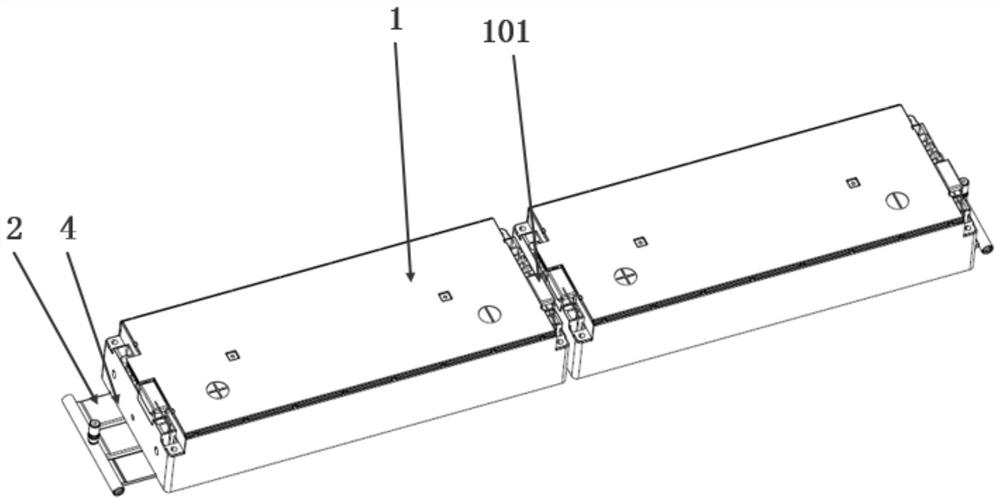
[0057] refer to figure 1 , figure 2 with Figure 4 , a thermal management control device for a self-heating battery, comprising a battery module 1 , a cooling system 2 , a self-heating system 3 and a heat conduction structure 4 .

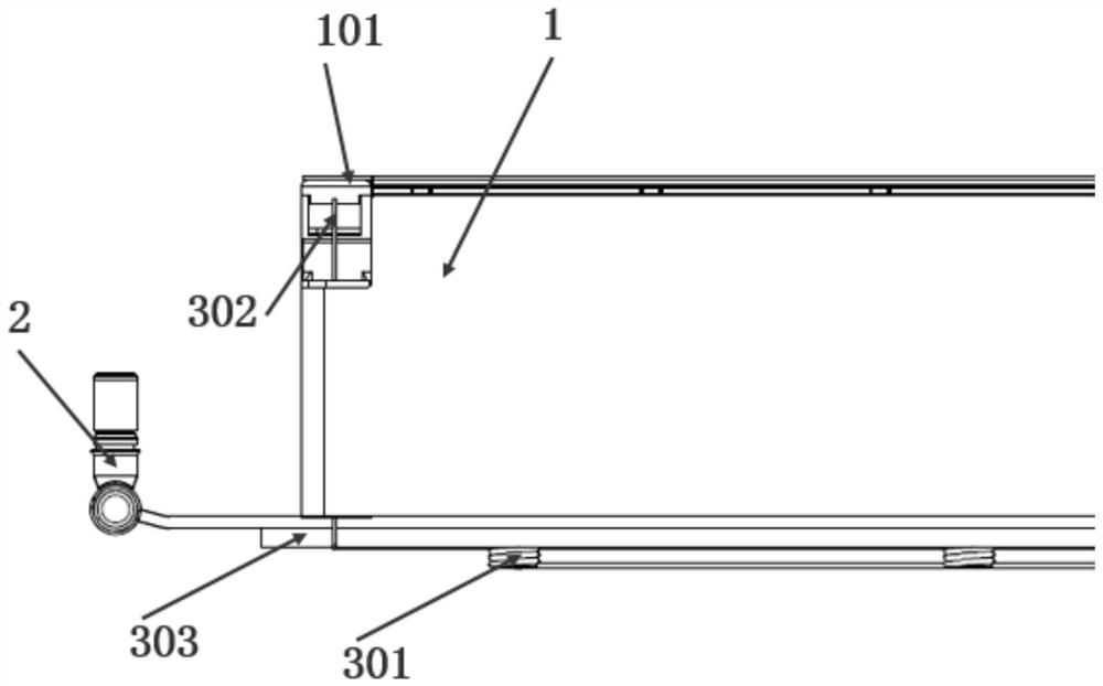
[0058] The battery module 1 is placed inside the battery pack. The positive and negative poles of the battery module 1 are provided with switch positive and negative poles 101; the positive and negative poles of the switch 101 contain IGBT switches; the IGBT switches are connected to the battery BMS. The battery BMS is mainly responsible for signal collection of the battery module 1 and controls the battery module 1 .

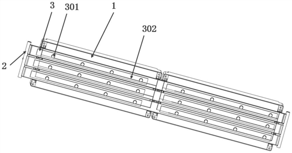
[0059] The cooling system 2 is arranged at the lower end of the battery module 1 .

[0060] The self-heating system 3 is fixed at the lower end of the cooling system 2, and is connected to the positive and negative poles of the battery module 1 in a loop;

[0061] refer to figure 2 with image 3 , the self-heating system 3 i...

Embodiment 2

[0070] This embodiment provides a battery assembly, including the self-heating battery thermal management control device in Embodiment 1. The battery assembly adopts a self-heating battery thermal management control device in Embodiment 1. Through the self-heating system, the efficient cooling of the battery assembly and the automatic heating function of the battery pack are realized, and the overall thermal management efficiency of the battery assembly is improved.

Embodiment 3

[0072] This embodiment provides an electric vehicle, including the battery assembly in the second embodiment. The battery assembly adopts the self-heating battery thermal management control device and self-heating system in Embodiment 1 to realize the efficient cooling of the battery assembly and the automatic heating function of the battery pack, which improves the overall thermal management efficiency of the battery assembly, thereby effectively ensuring The safety of electric vehicles reduces the cost of research and development.


PUM


Abstract

The invention relates to a self-heating battery thermal management control device, a battery assembly, an electric vehicle and a method. Comprising a battery module, a cooling system, a self-heating system and a heat conduction structure, the cooling system is arranged at the lower end of the battery module; the self-heating system is fixed at the lower end of the cooling system and connected with positive and negative electrodes of the battery module to form a loop; a heat conduction structure is arranged between the battery module and the cooling system. IGBT switches in the positive and negative electrodes of the switch control high-frequency on-off with the self-heating high-voltage wiring harness through a battery BMS: after high-frequency on-off is formed, electric field high-frequency change exists in the self-heating high-voltage wiring harness, and a large amount of heat is generated by induction current generated in the heater due to an electromagnetic induction phenomenon through spiral lines around the heater; therefore, the heating function of the heating fixing plate can be achieved, and the heating fixing plate can heat cooling liquid in the cooling system. According to the invention, efficient cooling of the power battery and automatic heating of the battery pack can be realized, and the overall thermal management efficiency of the power battery is improved.

Description

technical field [0001] The invention relates to the technical field of automobiles, in particular to a thermal management control device for a self-heating battery, a battery assembly, an electric vehicle and a method. Background technique [0002] As a key core component of new energy vehicles, the power battery's thermal management system is self-evident. The current mainstream battery thermal management system has a complex structure and cannot be integrated with the lower box. [0003] In view of the above problems, the application with publication number CN112820979A discloses a power battery thermal management system and a power battery thermal management control method, the system includes an expansion tank, an electric water pump, a power battery, a cooling module, a first solenoid valve, a second solenoid valve, heat exchanger with integrated expansion valve, third solenoid valve, air conditioner compressor and condensing, fuel heater assembly and fourth solenoid v...

Claims


Application Information

Patent Timeline
IPC IPC(8): H01M10/625H01M10/613H01M10/615H01M10/655H01M10/6571H01M10/633
CPCY02E60/10H01M10/6571H01M10/6554H01M10/655H01M10/633H01M10/625H01M10/613H01M10/615H01M10/6556
Inventor 王德平卢军孙焕丽于长虹许立超刘鹏李黎黎岳振东
Owner CHINA FIRST AUTOMOBILE
Why Eureka
Try Eureka