Thin film capacitor

A film capacitor and capacitor technology, applied in the field of capacitors, can solve the problems of increased heat generation and smaller heat dissipation area.

Pending Publication Date: 2022-04-12
XIAMEN FARATRONIC
View PDF0 Cites 0 Cited by
  • Summary
  • Abstract
  • Description
  • Claims
  • Application Information

AI Technical Summary

Problems solved by technology

However, when the volume of the film capacitor decreases, its heat dissipation area will decrease accordingly; when the current of the film capacitor incre

Method used


Image

  • Thin film capacitor
  • Thin film capacitor
  • Thin film capacitor

Examples


Embodiment 1

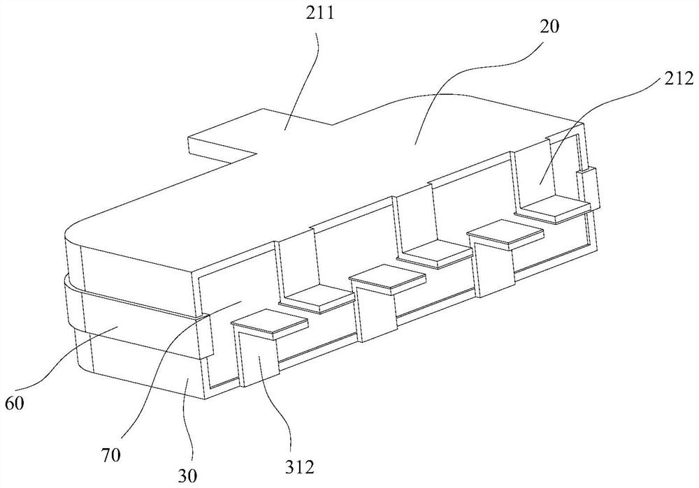
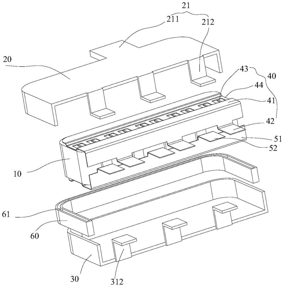
[0041] Such as Figure 1 to Figure 4 As shown, the film capacitor according to the embodiment of the present invention includes a capacitor core 10 , at least one first metal shell 20 , at least one second metal shell 30 , a first connection piece 40 and a second connection piece 50 .

[0042] Specifically, the first metal shell 20 and the second metal shell 30 are spliced ​​together through the insulator 60 to jointly define the accommodation cavity H; the first metal shell 20 is provided with a first lead-out terminal 21 , and the second metal shell The body 30 is provided with a second lead-out terminal 31; the first connecting piece 40 is connected with the capacitor core 10 and the first metal shell 20; the second connecting piece 50 is connected with the capacitor core 10 and the second metal shell 30; the capacitor The core 10 , the first connecting piece 40 and the second connecting piece 50 are arranged in the containing cavity H and sealed by a potting glue 70 .

[...

Embodiment 2

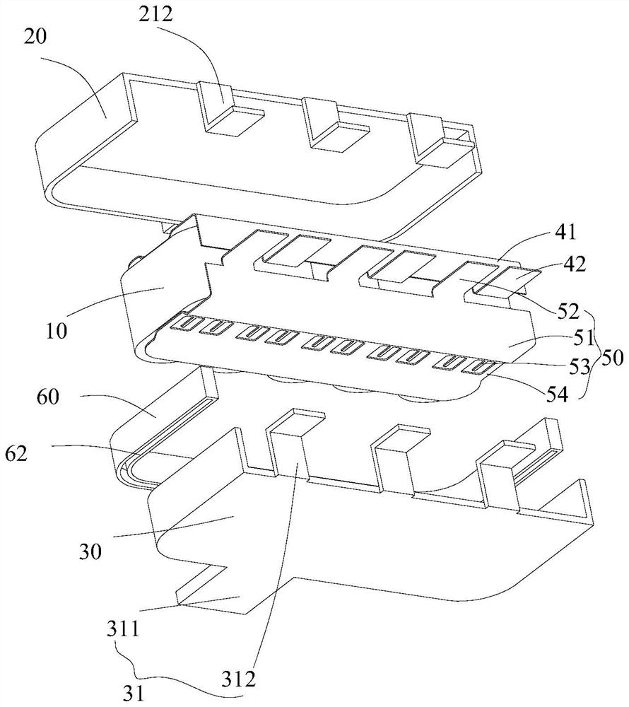
[0065] The structure and principle of this embodiment are roughly the same as those of the embodiment, the same place will not be described in detail, the difference is that in combination Figure 5 with Figure 6 , the arrangement of multiple cores in the capacitor core 10 is that the end faces are facing forward and backward, horizontally side by side, the first connecting piece body 41 of the first connecting piece 40 is L-shaped, and the first connecting terminal 42 is arranged on On the short limbs of the first connecting piece body 41 of the L shape, the long limbs of the first connecting piece body 41 of the L shape are arranged horizontally, so that the first connecting terminal 42 can be welded with the gold-sprayed surface of the capacitor core 10, and The connecting terminal is relatively soft, has a certain degree of plasticity, and is not easy to accumulate stress. When the connecting terminal is welded to the gold-sprayed surface, the welding point is on the conn...


PUM


Abstract

The invention discloses a thin film capacitor, which comprises a capacitor core, at least one first metal shell, at least one second metal shell, a first connecting sheet and a second connecting sheet, the first metal shell and the second metal shell are spliced together through an insulator to jointly define an accommodating cavity; the first metal shell is provided with a first leading-out terminal, and the second metal shell is provided with a second leading-out terminal; the first connecting sheet is connected with the capacitor core and the first metal shell; the second connecting sheet is connected with the capacitor core and the second metal shell; the capacitor core, the first connecting sheet and the second connecting sheet are arranged in the accommodating cavity and are sealed through pouring sealant; therefore, the capacitor has better heat dissipation capability while the current resistance capability is improved, and the thermal resistance of the product is greatly reduced.

Description

technical field [0001] The invention relates to the technical field of capacitors, in particular to a film capacitor. Background technique [0002] Film capacitors are widely used in electronic equipment, industrial control, automobiles and other fields. At present, film capacitors on the market are mainly composed of capacitor cores, bus bars, packaging shells, and filling resins. [0003] With the development and progress of technology, film capacitors need to have small volume, high current and higher power density. However, when the volume of the film capacitor decreases, its heat dissipation area will decrease accordingly; when the current of the film capacitor increases and the power density increases, its calorific value will increase accordingly. Thus, the heat dissipation of film capacitors becomes a prominent issue. Contents of the invention [0004] The present invention aims to solve one of the technical problems in the above-mentioned technologies at least ...

Claims


Application Information

Patent Timeline
IPC IPC(8): H01G4/33H01G2/08H01G4/005H01G4/224
Inventor 张龙陈渊伟杨邓颖
Owner XIAMEN FARATRONIC
Why Eureka
Try Eureka