Corrected PID temperature control method
A temperature control method and controller technology, applied in the direction of temperature control, control/regulation system, non-electric variable control, etc., can solve problems such as overshoot and temperature reverse regulation, and achieve convenient maintenance and use, cost reduction, and reliability. good readability
- Summary
- Abstract
- Description
- Claims
- Application Information
AI Technical Summary
Problems solved by technology
Method used
Image


Examples
Embodiment 1
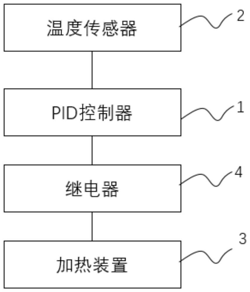
[0095] see figure 2 As shown, the embodiment of the present application provides a modified PID temperature control method, which is applied to the above-mentioned PID temperature control system, including:
[0096] S1, set the target temperature value t 0 , get the real-time temperature value t through the temperature sensor (k) ;
[0097] S2, calculate the calculation result PidOut of the PID controller at time k according to the PID algorithm formula (1) (k) .
[0098] The PID algorithm formula (1) is as follows:
[0099]
[0100] in,
[0101] K p is the proportional coefficient, which is obtained by data modeling calculation or its empirical value obtained according to the experimental method;
[0102] K i is the integral coefficient, which is calculated by data modeling or its empirical value is obtained according to the experimental method;
[0103] e (k) is the deviation between the target temperature value and the real-time temperature value at time k;
...
Embodiment 2
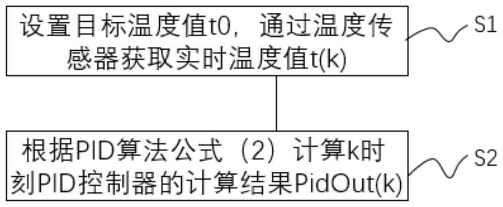
[0130] see image 3 As shown, the embodiment of the present application also provides a modified PID temperature control method, which is applied to the above-mentioned PID temperature control system, and the method includes:
[0131] S1, set the target temperature value t 0 , get the real-time temperature value t through the temperature sensor (k) ;
[0132] S2, calculate the calculation result PidOut of the PID controller at time k according to the PID algorithm formula (2) (k) .
[0133] The PID algorithm formula is as follows:
[0134]
[0135] in,
[0136] K p is the proportional coefficient, which is obtained by data modeling calculation or its empirical value obtained according to the experimental method;
[0137] K i is the integral coefficient, which is calculated by data modeling or its empirical value is obtained according to the experimental method;
[0138] e (k) is the deviation between the target temperature value and the real-time temperature value...
Embodiment 3
[0168] The embodiment of the present application also provides a modified PID temperature control method, which is applied to the above-mentioned PID temperature control system, and the method includes:
[0169] Set the target temperature value t 0 , get the real-time temperature value t through the temperature sensor (k) ;
[0170] Calculate the calculation result PidOut of the PID controller at time k according to the PID algorithm formula (1) (k) , the formula is as follows:
[0171]
[0172] in,
[0173] K p is the proportional coefficient, which is obtained by data modeling calculation or its empirical value obtained according to the experimental method;
[0174] K i is the integral coefficient, which is calculated by data modeling or its empirical value is obtained according to the experimental method;
[0175] e (k) is the deviation between the target temperature value and the real-time temperature value at time k;
[0176] A is the suppression parameter.
...
PUM
 Abstract
Description
Claims
Application Information
 - Generate Ideas
- Intellectual Property
- Life Sciences
- Materials
- Tech Scout
- Unparalleled Data Quality
- Higher Quality Content
- 60% Fewer Hallucinations
Browse by: Latest US Patents, China's latest patents, Technical Efficacy Thesaurus, Application Domain, Technology Topic, Popular Technical Reports.
© 2025 PatSnap. All rights reserved.Legal|Privacy policy|Modern Slavery Act Transparency Statement|Sitemap|About US| Contact US: help@patsnap.com