Pyrolysis gasification furnace

A technology of pyrolysis gasification and furnace body, which is applied in incinerators, lighting and heating equipment, combustion types, etc., can solve the problems of high production cost, large equipment occupied space, large carbon emissions, etc., and achieves reduction of waste disposal costs. , The effect of reducing the floor space of the equipment and reducing the floor space

Pending Publication Date: 2022-04-12
江苏交航环保科技有限公司
View PDF0 Cites 0 Cited by
  • Summary
  • Abstract
  • Description
  • Claims
  • Application Information

AI Technical Summary

Problems solved by technology

[0004] (1) Existing garbage pyrolysis gasifiers are bulky, complex in structure, high in production cost, and occupy a large space for equipment
[0005] (2) Existing pyrolysis gasification furnaces adopt a separate structure of the primary combustion chamber and the secondary combustion chamber, and the secondary combustion chamber requires an external heat source (electricity, diesel, natural gas, etc.) ), resulting in high waste disposal costs and large carbon emissions
[0006] (3) The temperature of the secondary combustion chamber of the existing pyrolysis gasifier is low, which cannot meet the requirements of fully decomposing dioxins, and it is difficult to meet the emission standards
[0007] (4) The pyrolysis flue gas produced in the primary combustion chamber of the existing pyrolysis gasification furnace is transported through the pipeline outside the furnace body; due to the low temperature of the pyrolysis gas, which contains a large amount of carbon particles and tar, it is It is easy to cause pipeline blockage, increase the amount of pipeline maintenance, and affect the continuous operation of the furnace

Method used


Image

  • Pyrolysis gasification furnace
  • Pyrolysis gasification furnace
  • Pyrolysis gasification furnace

Examples


Embodiment Construction

[0037] In order to make the object, technical solution and advantages of the present invention more clear, the present invention will be further described in detail below in conjunction with the examples. It should be understood that the specific embodiments described here are only used to explain the present invention, not to limit the present invention.

[0038] Aiming at the problems existing in the prior art, the present invention provides a pyrolysis gasifier. The present invention will be described in detail below with reference to the accompanying drawings.

[0039] Those of ordinary skill in the pyrolysis gasification furnace industry provided by the present invention can also adopt other steps to implement, figure 1 The pyrolysis gasifier provided by the present invention is only a specific embodiment.

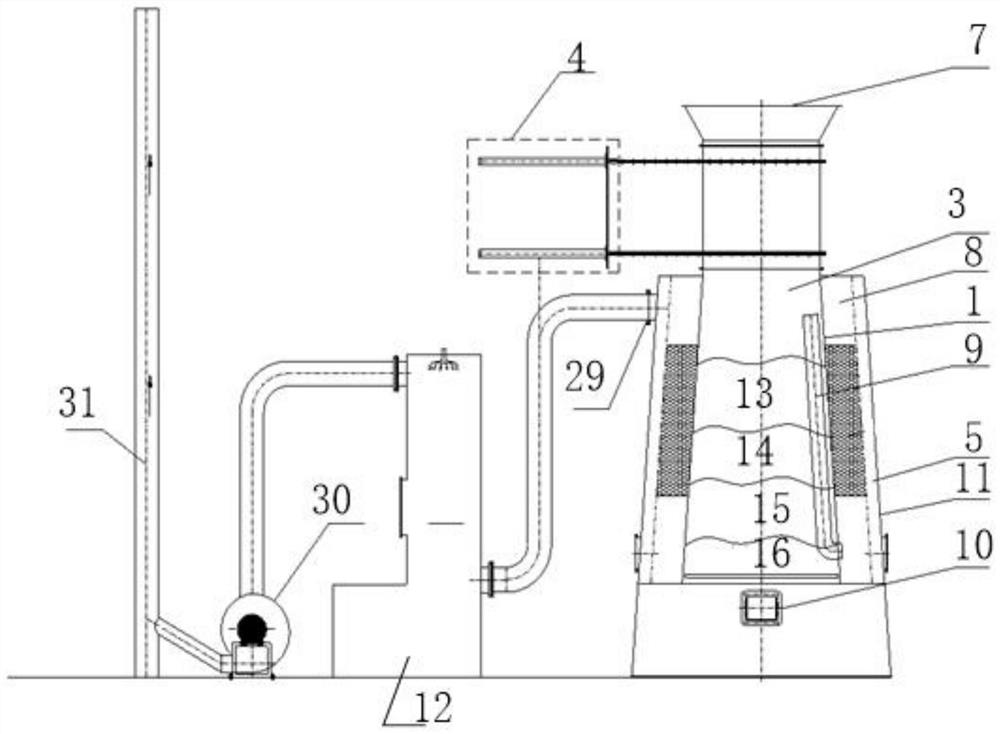
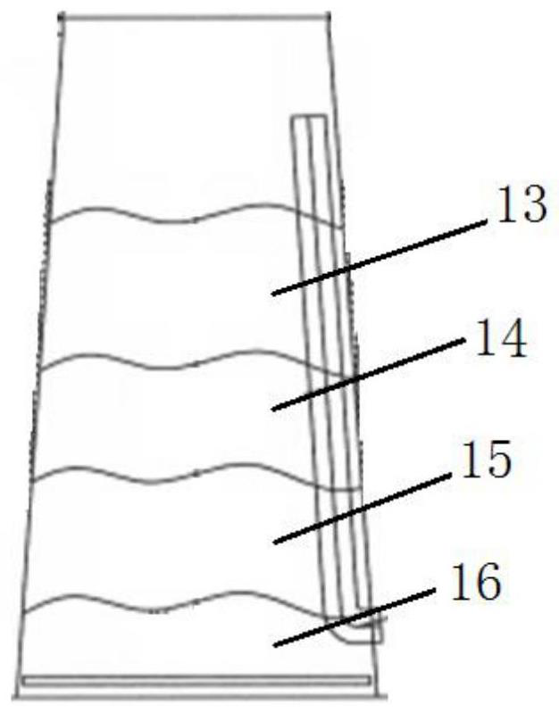
[0040] Such as Figure 1-Figure 2 As shown, the pyrolysis gasification furnace provided by the embodiment of the present invention is provided with a conical furnac...


PUM


Abstract

The invention belongs to the technical field of garbage pyrolysis and gasification equipment, and discloses a pyrolysis and gasification furnace which is characterized in that a feeding device is mounted at the upper end of a circular-truncated-cone-shaped furnace body, and the circular-truncated-cone-shaped furnace body is connected with a flue gas emission and purification device through a pipeline; the flue gas emission purification device is connected with the induced draft fan through a pipeline, and the induced draft fan is connected with the chimney; a tapered metal hearth is arranged in the circular-truncated-cone-shaped furnace body, and the upper end of the metal hearth is connected with a feeding device. The problems that an existing garbage pyrolysis gasification furnace is large in size, complex in structure and high in manufacturing cost are solved; the problems that in the garbage treatment process of a pyrolysis gasification furnace, an additional heat source is needed for heating a secondary combustion chamber, and consequently the garbage treatment cost is high and the carbon emission amount is large are solved. The problems that the temperature of a secondary combustion chamber of an existing pyrolysis gasification furnace is low, and the requirement for fully decomposing dioxin cannot be met are solved. The problem that a pyrolysis gas conveying pipeline is easily blocked by carbon deposition and tar is solved; the problem that the garbage is caked in the furnace and is difficult to fall is solved.

Description

technical field [0001] The invention belongs to the technical field of garbage pyrolysis gasification equipment, in particular to a pyrolysis gasification furnace. Background technique [0002] At present, garbage pyrolysis gasification refers to the process of breaking the macromolecules of organic components in garbage to produce small molecule gas, tar and residue under the condition of no oxygen or oxygen deficiency. Garbage pyrolysis gasification technology not only realizes the harmlessness, reduction and recycling of garbage, but also effectively overcomes the problem of dioxin pollution caused by garbage incineration, so it has become a garbage treatment technology with great development prospects. In the pyrolysis gasification process, a pyrolysis gasifier is required. However, the existing garbage pyrolysis gasifiers are bulky, complex in structure, high in production cost, and occupy a large area of ​​equipment. Existing waste pyrolysis gasifiers all adopt a str...

Claims


Application Information

Patent Timeline
Patent Type & Authority Applications(China)
IPC IPC(8): F23G5/027F23G5/16F23G5/44F23G5/50F23G7/00F23J15/02F23J15/04
Inventor 李志坚李根林
Owner 江苏交航环保科技有限公司
Why Eureka
Try Eureka