Oxygen tank batch inflation device for hospital supply department
The technology of an inflating device and an oxygen tank is applied in container filling methods, equipment loaded into pressure vessels, gas/liquid distribution and storage, etc., which can solve problems such as troublesome operation, affecting inflation efficiency, and low work efficiency, and avoid shaking , Avoid damage, high work efficiency
- Summary
- Abstract
- Description
- Claims
- Application Information
AI Technical Summary
Problems solved by technology
Method used
Image
Examples
Embodiment 1
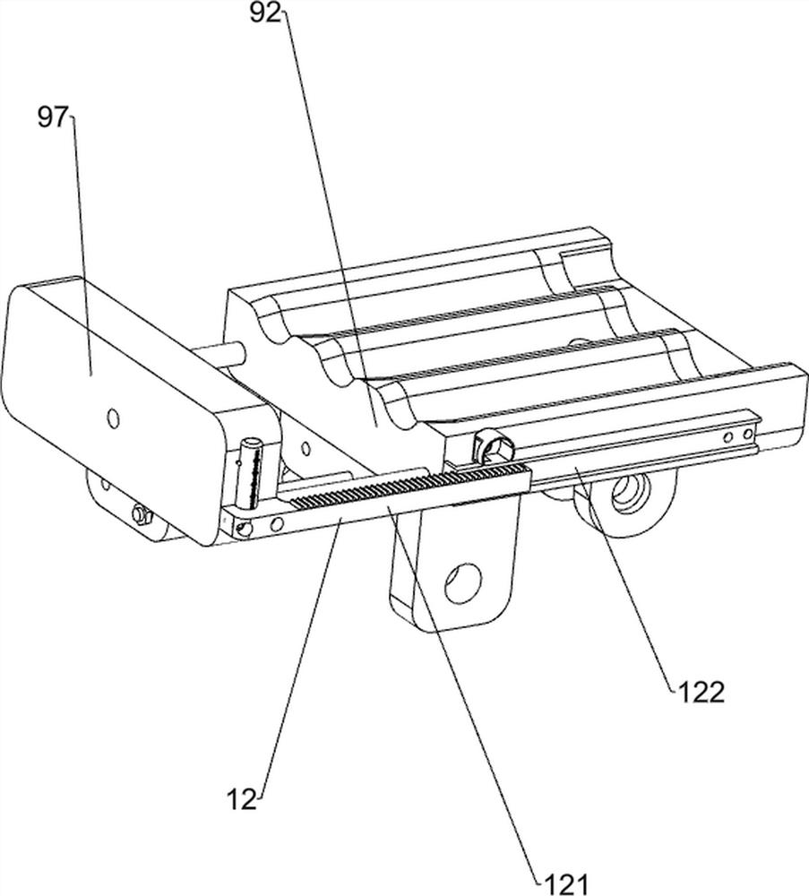
[0037] A batch inflation device for oxygen tanks used in hospital supply departments, such as Figure 1-Figure 8As shown, it includes a closed box 1, a support base 2, a support column 3, a heat dissipation window 4, a start button 51, a stop button 52, a support frame 6, a storage tank box 7, a feeding plate 71, a positioning rod 72, and a protective cover 8. The inflatable mechanism 9 and the unloading mechanism 10, the top right side of the support base 2 is fixed with a support column 3 symmetrically front and rear, and the airtight box 1 is fixedly connected between the top of the support column 3 on the front and rear sides and the left side of the top of the support base 2, The upper part of the airtight box 1 is embedded with a heat dissipation window 4, and the upper right part of the outer front side of the airtight box 1 is fixedly connected with a start button 51, and the upper right part of the outer front side of the airtight box 1 is fixedly connected with a stop...
Embodiment 2
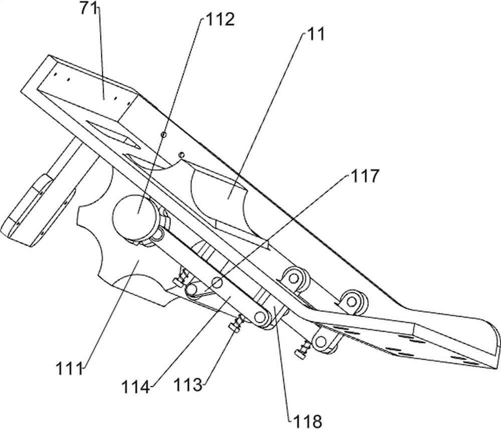
[0042] On the basis of Example 1, such as Figure 9-12 As shown, it also includes an interval feeding mechanism 11, and the interval feeding mechanism 11 includes a distribution drum 111, a positioning horizontal shaft 112, a reset short column 113, a linkage cross bar 114, a fixed bottom plate 115, a positioning cross bar 116, and a hinged short Rod 117, stressed short post 118, limit ring 119 and clamping short post 1110, the middle part of protective cover 8 is provided with positioning horizontal axis 112, and the middle part of positioning horizontal shaft 112 is fixedly connected with distribution roller 111 in the circumferential direction. 8. There are reset short columns 113 at intervals on the left side of the inner bottom, and a linkage cross bar 114 is provided slidingly between the reset short columns 113 on the left and right sides. The middle side of the bottom of the feeding plate 71 is fixedly connected with a fixed bottom plate 115, and the lower part of the f...
Embodiment 3
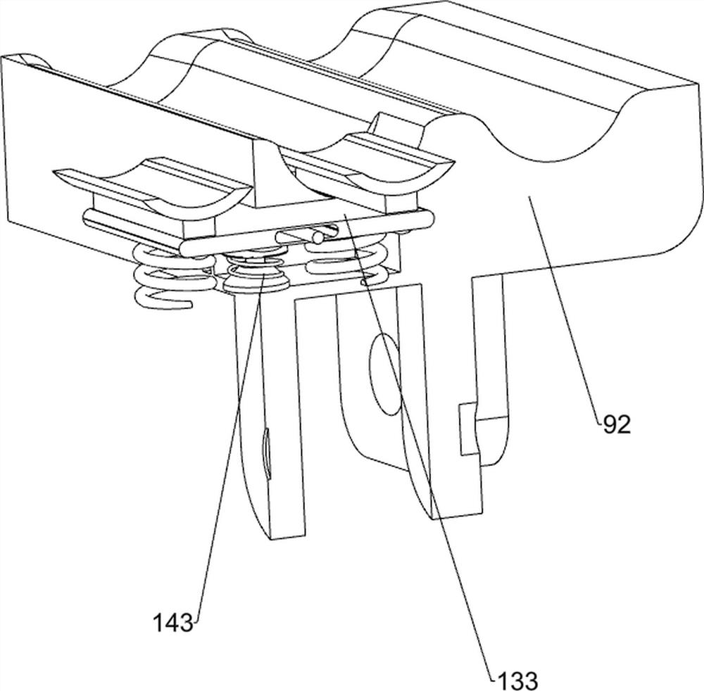
[0047] On the basis of embodiment 1 and embodiment 2, such as Figure 13-Figure 15 As shown, buffer mechanism 13 is also included, and buffer mechanism 13 includes buffer sponge block 131, buffer bottom plate 132 and buffer short post 133, and the inner rear side of feeding box 101 is fixed with buffer sponge block 131, and the bottom of feeding box 101 The left and right sides are symmetrically fixed with buffer stubs 133 , and the buffer bases 132 are slidably provided between the left and right sides of the buffer studs 133 .
[0048] Also includes a retaining mechanism 14, the retaining mechanism 14 includes a telescopic solenoid valve 141, a material retaining plate 142, a second pressure sensor 143 and a tilting frame 144, the lower side of the right part of the bottom of the loading plate 71 is provided with a telescopic solenoid valve 141, telescopic The solenoid valve 141 is connected with a material blocking plate 142 , a second pressure sensor 143 is provided on the...
PUM
 Abstract
Description
Claims
Application Information
 - R&D Engineer
- R&D Manager
- IP Professional
- Industry Leading Data Capabilities
- Powerful AI technology
- Patent DNA Extraction
Browse by: Latest US Patents, China's latest patents, Technical Efficacy Thesaurus, Application Domain, Technology Topic, Popular Technical Reports.
© 2024 PatSnap. All rights reserved.Legal|Privacy policy|Modern Slavery Act Transparency Statement|Sitemap|About US| Contact US: help@patsnap.com


