Electrically-controlled hydraulic proportional pressure reducing valve

A proportional pressure reducing valve and electronically controlled hydraulic technology, which is applied in the direction of fluid pressure actuators, servo motor components, mechanical equipment, etc., can solve the problems of high cost and increase the cost of hydraulic systems, and achieve the goal of reducing costs and increasing the scope of use Effect

Pending Publication Date: 2022-04-12
WEIHAI WEINONG TECH DEV CO LTD
View PDF0 Cites 0 Cited by
  • Summary
  • Abstract
  • Description
  • Claims
  • Application Information

AI Technical Summary

Problems solved by technology

[0003] The pressure reducing valve is a commonly used hydraulic component in the hydraulic system, and the general proportional pressure reducing valve. If the pressure reducing range is adjusted, the entire valve core and sleeve need to be replaced to adjust different area ratios, which is costly. At the same time, for large oil return The decompression system requires a proportional solenoid with a large stroke, which further increases the cost of the hydraulic system

Method used


Image

  • Electrically-controlled hydraulic proportional pressure reducing valve
  • Electrically-controlled hydraulic proportional pressure reducing valve
  • Electrically-controlled hydraulic proportional pressure reducing valve

Examples


Embodiment Construction

[0051] In order to make the technical problems, technical solutions and beneficial effects to be solved by the present application clearer, the present application will be further described in detail below in conjunction with the accompanying drawings and embodiments. It should be understood that the specific embodiments described here are only used to explain the present application, and are not intended to limit the present application.

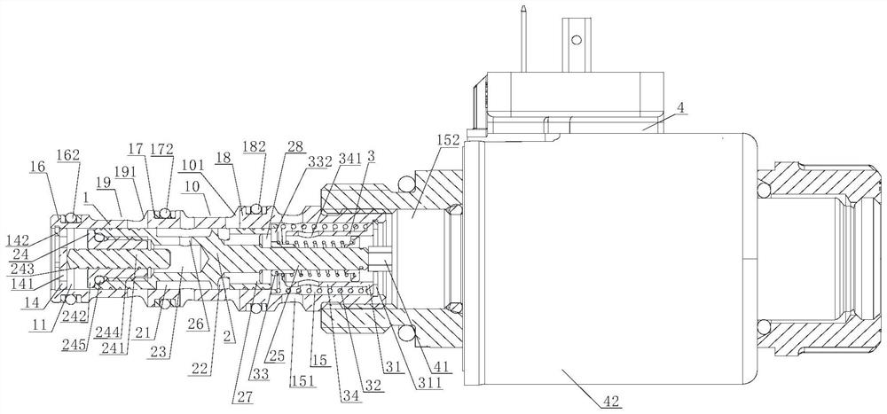
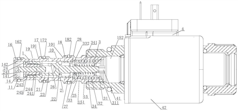
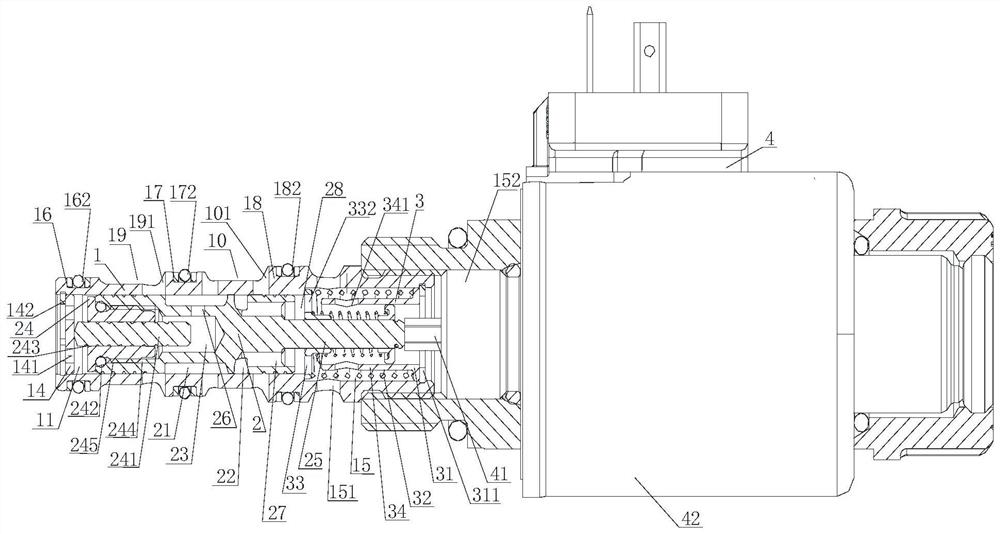
[0052] The electronically controlled hydraulic proportional pressure reducing valve provided in the embodiment of the present application will now be described. The electronically controlled hydraulic proportional pressure reducing valve is as Figure 1 to Figure 13 Shown:

[0053] The invention is installed in the hydraulic integrated block, and the hydraulic integrated block is provided with a channel port, and the channel port is provided with an inlet and an outlet, so as to reduce the inlet pressure to the required outlet pressure.

...


PUM


Abstract

The electronic control hydraulic proportional pressure reducing valve is provided with a valve body and a valve element, an adjusting cavity is formed in the valve body, the valve element is arranged in the adjusting cavity, and the side face of the valve element abuts against the side wall of the adjusting cavity to form sliding connection; a pilot valve cavity and a pilot valve cover are arranged at one end of the valve element, the pilot valve cover covers the outer end of the pilot valve cavity, and the pilot valve cover is detachably and fixedly connected with the valve element; the pilot valve cover is provided with a pilot valve sleeve and a pilot valve rod, and the pilot valve rod is inserted into and penetrates through the pilot valve sleeve to form movable connection; one end of the pilot valve rod is inserted into the pilot valve cavity, and the other end of the pilot valve rod abuts against the baffle; the side face of the valve element is provided with an adjusting groove communicated with the pilot valve cavity. The two ends of the valve body are provided with ports, the baffle is fixedly arranged in one port, and the other port is provided with a control mechanism. A circulating hole communicated with the channel opening is formed in the side surface of the valve body; the control mechanism adjusts the position of the valve element in the adjusting cavity, adjusts the pressure of hydraulic oil entering the pilot valve cavity through the inlet and conveys the hydraulic oil in the pilot valve cavity to the outlet.

Description

technical field [0001] The present application belongs to the technical field of pressure reducing valves, and more specifically relates to an electronically controlled hydraulic proportional pressure reducing valve. Background technique [0002] The pressure reducing valve is a valve that reduces the inlet pressure to a certain required outlet pressure through adjustment, and relies on the energy of the medium itself to keep the outlet pressure automatically stable; from the perspective of fluid mechanics, the pressure reducing valve is a local resistance that can The variable throttling element, that is, by changing the throttling area, the flow rate and the kinetic energy of the fluid are changed, resulting in different pressure losses, so as to achieve the purpose of decompression; then rely on the adjustment of the control and regulation system to balance the fluctuation of the pressure behind the valve , so that the pressure behind the valve remains constant within a c...

Claims


Application Information

Patent Timeline
Patent Type & Authority Applications(China)
IPC IPC(8): F15B13/02
Inventor 周逢春于强华王华军
Owner WEIHAI WEINONG TECH DEV CO LTD
Why Eureka
Try Eureka